Hummingbird Moths.....we had them in Northern IL.
Gosh ! I shot this 10 years ago up in Duluth....
This forum allows conversation on non-controversial topics, therefore no politics or religion. "The Campfire" is an area meant for casual, civil discussions. Deliberate anti-social activity including personal insults, profanity, pornography, racism, threats and purposely inflammatory posts may result in suspension of forum access or possibly a permanent ban from GSR.
The words insight and incite are pronounced the same. But one of them will get you banned and the other will not. Before hitting the Submit button be certain which of the two better describes your post.
Required reading for all forum users!!!
Welcome!
Register to access the full functionality of the GSResources forum. Until you register and activate your account you will not have full forum access, nor will you be able to post or reply to messages.
A note to new registrants...
All new forum registrations must be activated via email before you have full access to the forum.
A Special Note about Email accounts!
DO NOT SIGN UP USING hotmail, outlook, gmx, sbcglobal, att, bellsouth or email.com. They delete our forum signup emails.
A note to old forum members...
I receive numerous requests from people who can no longer log in because their accounts were deleted. As mentioned in the forum FAQ, user accounts are deleted if you haven't logged in for the past 6 months. If you can't log in, then create a new forum account. If you don't get an error message, then check your email account for an activation message. If you get a message stating that the email address is already in use, then your account still exists so follow the instructions in the forum FAQ for resetting your password.
Have you forgotten your password or have a new email address? Then read the forum FAQ for details on how to reset it.
Any email requests for "can't log in anymore" problems or "lost my password" problems will be deleted. Read the forum FAQ and follow the instructions there - that's what we have one for...
If you are a returning visitor who never received your confirmation email, then odds are your email provider is blockinig emails from our server. The only thing that can be done to get around this is you will have to try creating another forum account using an email address from another domain.
If you are a returning visitor to the forum and can't log in using your old forum name and password but used to be able to then chances are your account is deleted. Purges of the databases are done regularly. You will have to create a new forum account and you should be all set.
Hummingbird Moths.....we had them in Northern IL.


. . . . . . is 3 years after a huge fire in Kootenay National park.
.
Kootenay Park - Rebirth by soates50, on Flickr

Last night
A few years ago our daughter mentioned "pier jumping", and we had to ask what she meant, and that kinda startled her. And lead into discussion of how it was something most kids would do, and would snicker about how thier parents would not approve or specifically prohibit just because it might appear to be hazardous but really is no danger at all, or so they thought at the time.
Note: As can see in photo by the wett area, is a group that had been doing this repeatidly. RUnning and jumping from the higher portion of the pier. One kid was doing summersaults and tucks and such like maybe knew classic springboard dives. Also keep in mind that are large ballast stones along edge of pier maybe 2 foot under surface of water (lake side). I saw one kid run and slip, momentum carried him on off the upper level and he barley cleared the lower edge.
.

 Looking thru windows. by Glen Brenner, on Flickr
 Looking thru windows. by Glen Brenner, on Flickr
Does look quite simple at first.
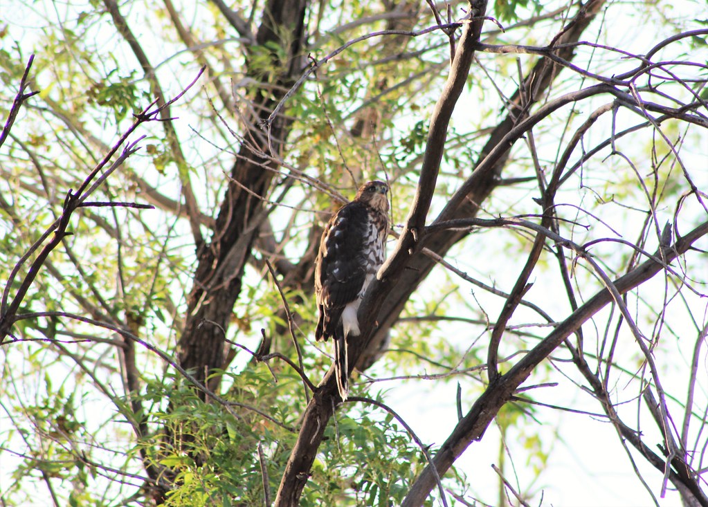
 IMG_5911 by Scott Marvin, on Flickr


