.png "Powered by vBulletin")
This modification applies specifically to the 1982-83 GS1100EZ/ED harnesses where you are planning or have completed a Coil or Ignition relay modification. It also generally applies to any GS1100E and several other GS's can derive some benefit as well although the original harnesses on those bikes are not as poorly designed as the adapted EZ/ED harnesses.
The PROBLEM:
On the GS 1100EZ/ED R handlebar switch connector to the harness there are connector wiring loops for all three primary power circuits
Strictly speaking only the O/W (IGNITION) is necessary to allow the Kill and Start switches to function. The O/R and O/G are some factory convenience for comparability with other models (or maybe a factory installed brain fart).
The O/G and O/R are even larger loads than the O/W so the marginal benefit of cross compatibility would seem out weighted by the potential voltage drop through these connections. On the EZ/ED it is especially bad because the loops are accomplished with back to back connectors. That means that both the O/R and O/G circuits have 8 crimped connections and 4 interference fit contacts in each loop!!! It would seem that this was perhaps intended to be a harness heating feature?????
SOLUTIONS:
So even if you don't have a Ignition Relay Modification planned, your headlamp and signal lights will probably all get brighter if you remove both the O/R and O/G loops going through these back to back connectors. You will still be able to disconnect your right handlebar switch as these looks have nothing to do with it either.
(What is typically called a coil relay mod might actually be an IGNITION relay mod if it powers both coils and ignitor).
If you are going to do an IGNITION/COIL relay modification or add a SSPB then you know that you have to reroute the output of your KILL switch. The KILL switch OUTPUT has to be disconnected from the O/W circuit and instead be routed to the new device that is going to switch on the O/W IGNITION power. That new device is either a mechanical relay for the IGNITION/COIL Relay Mod or the SSPB- Pin3 for that installation. Typically this new device is in the rear of the bike near the battery.
A mechanical relay should be isolation mounted to reduce the vibration that it sees. The device will last much longer if you mount it through some type of rubber or other compliant mounting tab. The SSPB is a OEM fuse box replacement so the mounting locations is also close to the battery.
This is where another one of the GS Suzuki brain fart designs is actually going to help you. Most all GS Suzuki's have a G/W and W/R stator wire loop going to a loop in the harness. On many of these bikes this G/W (or Lg/W) and W/R wiring loop should be eliminated when you wire your three (3 phase) stator wires directly to the R/R (SHUNT or SERIES). So after that is completed you have two spare wires in your harness that can be used for other purposes.
In my Coil relay Modification write up as well in the SSPB installation guide I recommend routing the Kill switch out put using one of these wires to avoid having to add yet any more wire. In the figure below, I chose the Lg/W wire. It comes out of the harness where your original R/R connections come out. That is the same place as the original RED primary which goes to the "T".
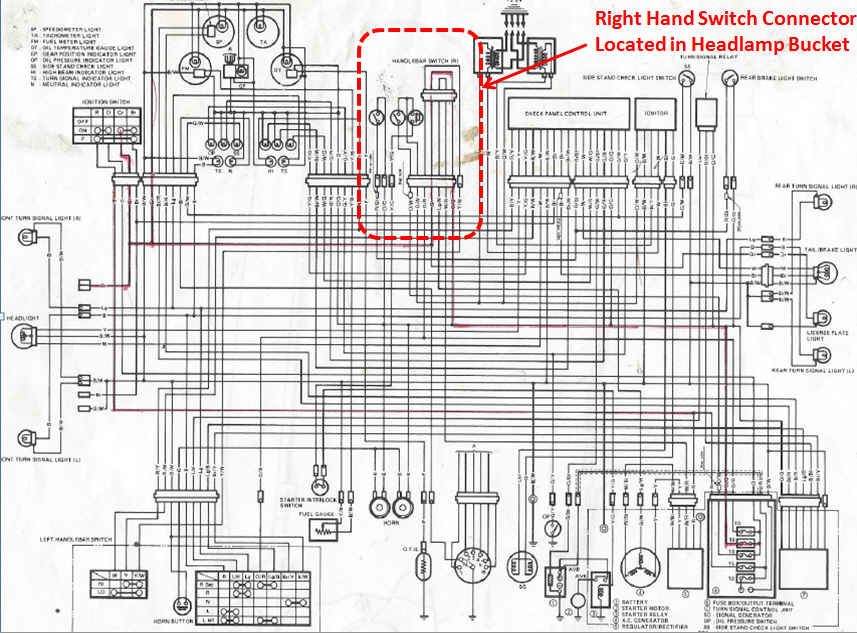
The connectors that I'm discussing here are in the headlamp bucket and can be easily identified by the O/W wires that go in and out. They are circled with a dashed red line on the schematic.
In the figure below you will see two handlebar schematics. If you make the modifications you will see that you are left with only two O/W wires remaining going through the connector. So if you want to be able to unplug your right hand switch from the harness then you can leave the connector in place for these two wires. All the rest of the wires are part of the harness and serve no purpose going through the two connectors and should be wired directly at the harness side of the connector. When you add the Relay Mod or SSPB there is no longer significant current running through the Kill switch so there is no concern about retaining the connector with only the two wires.
If you study the two schematics you will see they are very similar. The only difference is in the O/W wires on the harness side and is summarized below:
For IGNITION/Coil Relay Mod:
the O/W with red tab powers the Kill Switch.
The harness side of the O/W must be disconnected from the kill switch so that the power can be applied from the relay else where.
For the SSPB Mod:
The O/W with red tab is powered by the SSPB and it must be connected to the O/W at the harness side of the connector to power the rest of the ignition circuit. No other connections are required.
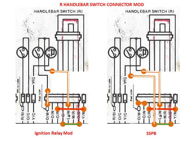
One fine point to make is that in fact both the IGNITION/COIL relay Mod or the SSPB mod could have been done identically (see the right hand side). In either case both need to have the Kill switched powered from a switched source. The O/G provides that nicely and it is available right at the RH switch connector.
CONCLUSIONS:
If you don't have a GS1100EZ/ED you might still be able to benefit from this discussion. See if there are O/R or O/G circuit looks through this connector. You can remove them. Or if you are doing am Ignition mod, use one of the stator loop wires as the way to control you IGNITION powering device.
P.S. This revelation of making these modification originated while Chef1366 was doing his SSPB install. I generalize it a bit to apply to most of the GS's.
.png)
The PROBLEM:
On the GS 1100EZ/ED R handlebar switch connector to the harness there are connector wiring loops for all three primary power circuits
- O/W IGNITION,
- O/R HEADLAMP
- O/G SIGNAL.
Strictly speaking only the O/W (IGNITION) is necessary to allow the Kill and Start switches to function. The O/R and O/G are some factory convenience for comparability with other models (or maybe a factory installed brain fart).
The O/G and O/R are even larger loads than the O/W so the marginal benefit of cross compatibility would seem out weighted by the potential voltage drop through these connections. On the EZ/ED it is especially bad because the loops are accomplished with back to back connectors. That means that both the O/R and O/G circuits have 8 crimped connections and 4 interference fit contacts in each loop!!! It would seem that this was perhaps intended to be a harness heating feature?????
SOLUTIONS:
So even if you don't have a Ignition Relay Modification planned, your headlamp and signal lights will probably all get brighter if you remove both the O/R and O/G loops going through these back to back connectors. You will still be able to disconnect your right handlebar switch as these looks have nothing to do with it either.
(What is typically called a coil relay mod might actually be an IGNITION relay mod if it powers both coils and ignitor).
If you are going to do an IGNITION/COIL relay modification or add a SSPB then you know that you have to reroute the output of your KILL switch. The KILL switch OUTPUT has to be disconnected from the O/W circuit and instead be routed to the new device that is going to switch on the O/W IGNITION power. That new device is either a mechanical relay for the IGNITION/COIL Relay Mod or the SSPB- Pin3 for that installation. Typically this new device is in the rear of the bike near the battery.
A mechanical relay should be isolation mounted to reduce the vibration that it sees. The device will last much longer if you mount it through some type of rubber or other compliant mounting tab. The SSPB is a OEM fuse box replacement so the mounting locations is also close to the battery.
This is where another one of the GS Suzuki brain fart designs is actually going to help you. Most all GS Suzuki's have a G/W and W/R stator wire loop going to a loop in the harness. On many of these bikes this G/W (or Lg/W) and W/R wiring loop should be eliminated when you wire your three (3 phase) stator wires directly to the R/R (SHUNT or SERIES). So after that is completed you have two spare wires in your harness that can be used for other purposes.
In my Coil relay Modification write up as well in the SSPB installation guide I recommend routing the Kill switch out put using one of these wires to avoid having to add yet any more wire. In the figure below, I chose the Lg/W wire. It comes out of the harness where your original R/R connections come out. That is the same place as the original RED primary which goes to the "T".
The connectors that I'm discussing here are in the headlamp bucket and can be easily identified by the O/W wires that go in and out. They are circled with a dashed red line on the schematic.
In the figure below you will see two handlebar schematics. If you make the modifications you will see that you are left with only two O/W wires remaining going through the connector. So if you want to be able to unplug your right hand switch from the harness then you can leave the connector in place for these two wires. All the rest of the wires are part of the harness and serve no purpose going through the two connectors and should be wired directly at the harness side of the connector. When you add the Relay Mod or SSPB there is no longer significant current running through the Kill switch so there is no concern about retaining the connector with only the two wires.
If you study the two schematics you will see they are very similar. The only difference is in the O/W wires on the harness side and is summarized below:
For IGNITION/Coil Relay Mod:
the O/W with red tab powers the Kill Switch.
The harness side of the O/W must be disconnected from the kill switch so that the power can be applied from the relay else where.
For the SSPB Mod:
The O/W with red tab is powered by the SSPB and it must be connected to the O/W at the harness side of the connector to power the rest of the ignition circuit. No other connections are required.
One fine point to make is that in fact both the IGNITION/COIL relay Mod or the SSPB mod could have been done identically (see the right hand side). In either case both need to have the Kill switched powered from a switched source. The O/G provides that nicely and it is available right at the RH switch connector.
CONCLUSIONS:
If you don't have a GS1100EZ/ED you might still be able to benefit from this discussion. See if there are O/R or O/G circuit looks through this connector. You can remove them. Or if you are doing am Ignition mod, use one of the stator loop wires as the way to control you IGNITION powering device.
P.S. This revelation of making these modification originated while Chef1366 was doing his SSPB install. I generalize it a bit to apply to most of the GS's.


Comment