.png "Powered by vBulletin")
I have just completed the electrical repair and upgrade on the wiring of my GS550/650B motorcycle. It includes an upgrade from a single fuse system that powers the complete electrical setup on the bike to a system with six fuses as well as a general upgrade of wiring within the 33 year old harness.
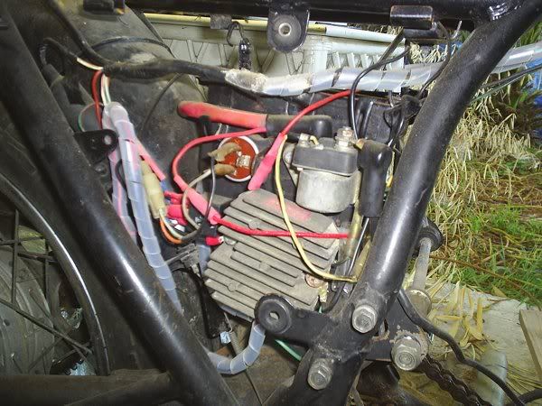
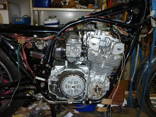
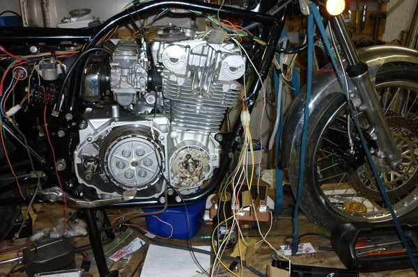
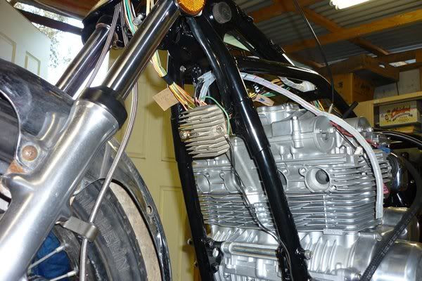
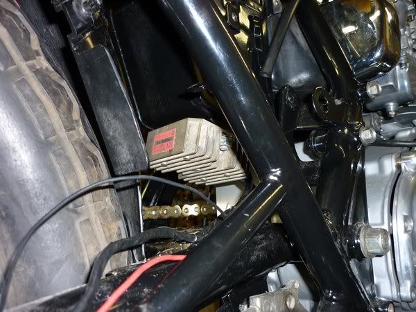
First a picture of the old single fuse setup where everything on the bike ran through this fuse to receive power from the battery, also the charging went through this fuse to the battery as well from the R/R and stator.
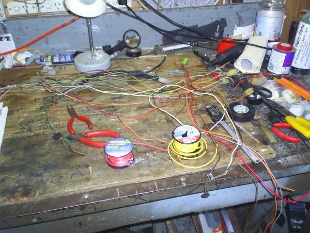
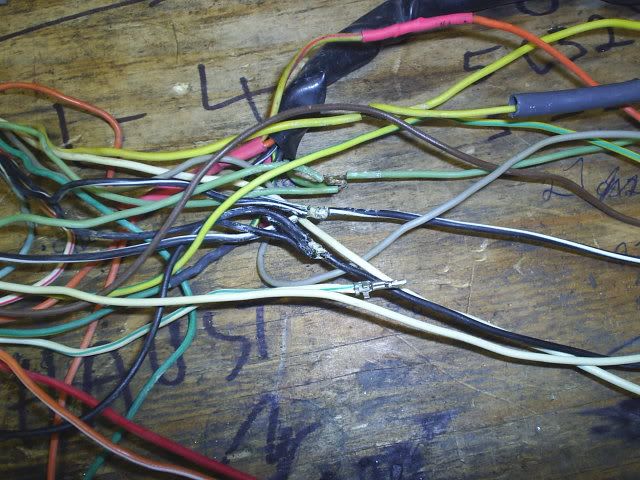
After removing the complete harness from the frame I unwrapped the electrical tape and other protective coverings from it that had gathered over the last 30 odd years and was left with a bunch of loose wires on the work bench.
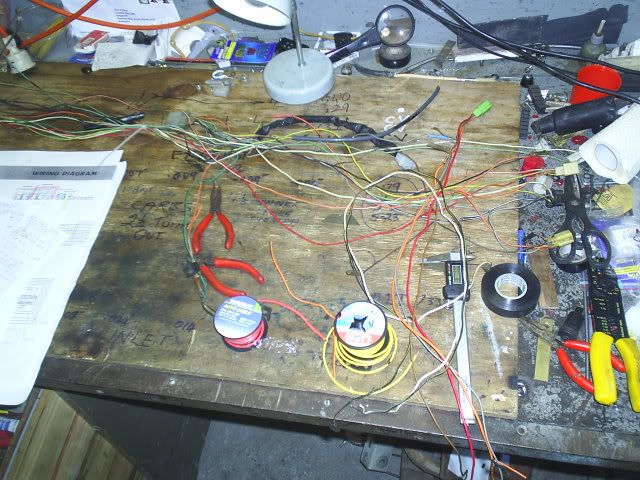
I zip tied the loom in 5 or 6 places to keep the wires in place and then cleaned each individual wire down with unleaded petrol. After they were all clean I then sprayed brake cleaner on a rag and wiped each of the wires clean with that. A quick blow off with compressed air and it all looked like new. A very messy job though. I used gloves to protect my hands from the petrol and brake cleaner.
I then did a trial fit of the loom on the frame and made note of which wires needed to be lengthened, etc.
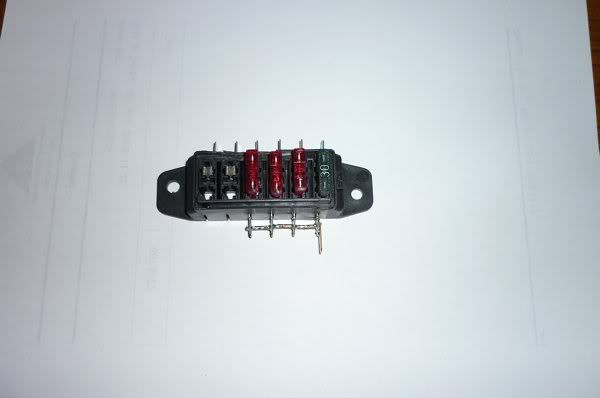
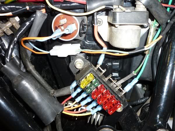
I cut out the bodged up stuff that had been done to the loom over the years. I also ran the new wires required for the 6 fuse upgrade. That included the three 15 amp wires, one an EARTH from end to end that pigtails would run off, the major RED wire from the fuse box to the ignition switch and the green wires from the ignition switch back to the fuse box to feed the other four fuses that would go to the circuits for the 1) coils, kill sw. & starter button, 2) blinkers, 3) lights & 4) front & rear brake lights, horn, oil pressure & neutral light.
I spliced in the wires from the RH GS650 switch that I had decided to use. That meant that the ON/OFF switch for the lights was now on the RH side of the bars instead of being on the LH side with the dimmer switch. I also wired up the passing button on the LH switch. BTW the LH switch is from a XJ650 Yamaha (sorry, but has a much better choke arrangement than the plastic thing on the GS bikes).
I lengthened the wires, stripped and soldered them and shrunk the heatshrink over the joins. I also cut away and replaced old bullet connectors with new ones as necessary.
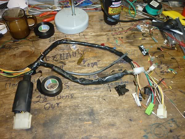
I then taped up the wiring loom with new electrical tape ready for the final fitment to the frame.
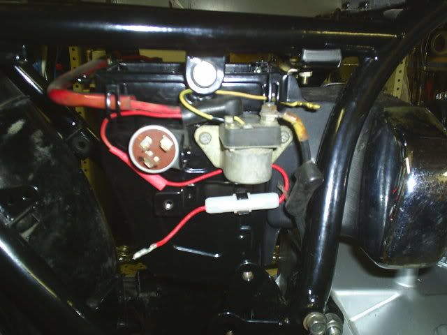
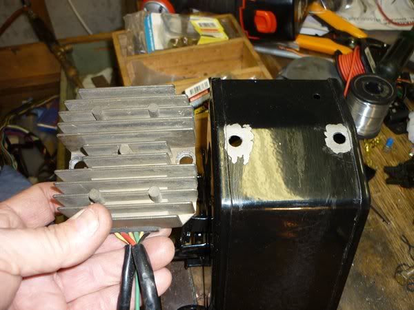
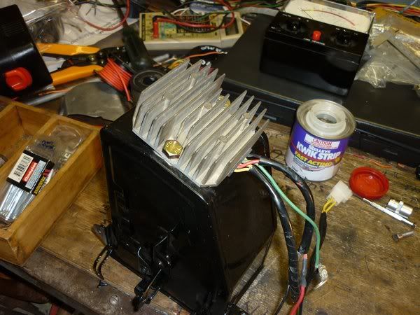
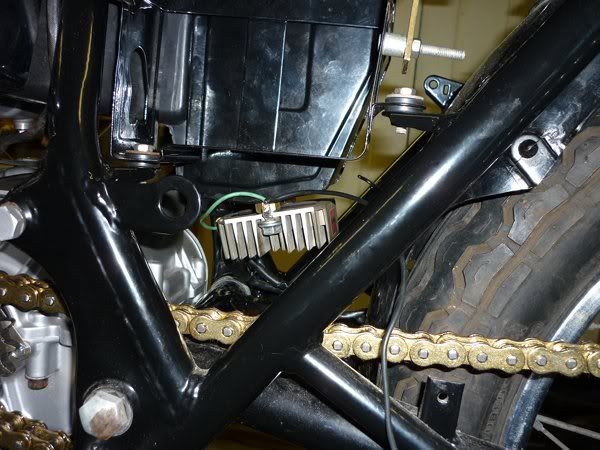
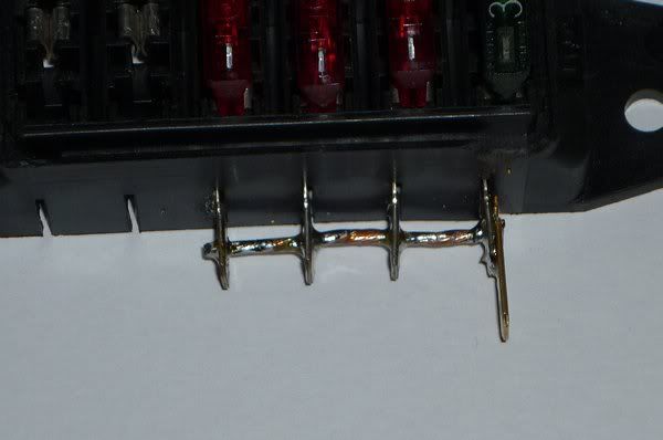
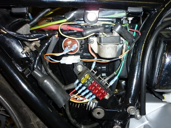
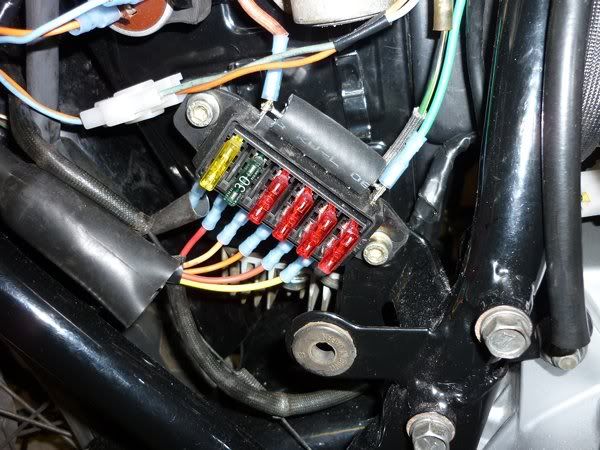
I still had to mount the new fuse box and the Honda R/R to the frame. After the wiring was covered with the new tape with 1/3 overlap the loom was fitted back onto the bike/frame. A couple of the pig tails I had done off the new 15 amp earth wire were a bit short so I had to lengthen them appropriately.
First a picture of the old single fuse setup where everything on the bike ran through this fuse to receive power from the battery, also the charging went through this fuse to the battery as well from the R/R and stator.
After removing the complete harness from the frame I unwrapped the electrical tape and other protective coverings from it that had gathered over the last 30 odd years and was left with a bunch of loose wires on the work bench.
I zip tied the loom in 5 or 6 places to keep the wires in place and then cleaned each individual wire down with unleaded petrol. After they were all clean I then sprayed brake cleaner on a rag and wiped each of the wires clean with that. A quick blow off with compressed air and it all looked like new. A very messy job though. I used gloves to protect my hands from the petrol and brake cleaner.
I then did a trial fit of the loom on the frame and made note of which wires needed to be lengthened, etc.
I cut out the bodged up stuff that had been done to the loom over the years. I also ran the new wires required for the 6 fuse upgrade. That included the three 15 amp wires, one an EARTH from end to end that pigtails would run off, the major RED wire from the fuse box to the ignition switch and the green wires from the ignition switch back to the fuse box to feed the other four fuses that would go to the circuits for the 1) coils, kill sw. & starter button, 2) blinkers, 3) lights & 4) front & rear brake lights, horn, oil pressure & neutral light.
I spliced in the wires from the RH GS650 switch that I had decided to use. That meant that the ON/OFF switch for the lights was now on the RH side of the bars instead of being on the LH side with the dimmer switch. I also wired up the passing button on the LH switch. BTW the LH switch is from a XJ650 Yamaha (sorry, but has a much better choke arrangement than the plastic thing on the GS bikes).
I lengthened the wires, stripped and soldered them and shrunk the heatshrink over the joins. I also cut away and replaced old bullet connectors with new ones as necessary.
I then taped up the wiring loom with new electrical tape ready for the final fitment to the frame.
I still had to mount the new fuse box and the Honda R/R to the frame. After the wiring was covered with the new tape with 1/3 overlap the loom was fitted back onto the bike/frame. A couple of the pig tails I had done off the new 15 amp earth wire were a bit short so I had to lengthen them appropriately.


Comment