.png "Powered by vBulletin")
So, once you built the unit it wouldn't be just plug and play? That's really what I am hoping for. Also as far as getting the epoxy off of the old units, here is a method that some people have used to get to their discontinued synth chips by Roland.
-
-
In my case it's almost a plug and play. You would need to run one additional wire to the stop lamp circuit.Comment
-
Awoken from a deep slumber
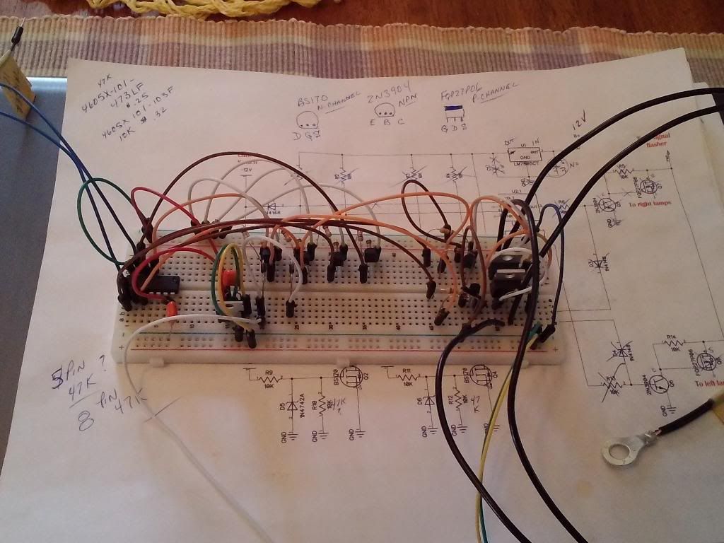
TSCU V1 manual operation only.
V2 with auto cancel to follow as time permits.
I had the triggers wired up incorrectly today but I ran out of time with all the other gongs on to give it a second try. I will fire it up again in a day or two and see if it works as I think it should.
Basically it's a LM556 (dual 555 timer) operating as a bi-stable flip-flop and driving P-channel MOSfets used as a high side switch for the turn signal lamps. N-channel MOSfets are used to trigger and cancel the LM556.
 Last edited by rustybronco; 04-20-2014, 11:51 PM.
Comment
-
I still need to wire up the two diodes that inhibit operating both side turn signals at once. Other than that she's a working example of a manually operated replacement TSCU.
The diagram for this is close to being complete. I still need to finalize a few pads, purchase a couple different resistor networks (10 pin bussed-8 pin isolated), some .33µF mylar caps then I can finalize the PCB layout.
More is in process... Stay tuned.
Comment
-
-
Putzing with it as I can. What I really need to do is see if I can separate the potted board from the original TSCU's housing, then we'll know if the 'self cancel' version of this will fit.Comment
-
Originally posted by rustybronco View Post
Looks like you will get there, just keep it up.
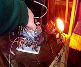
I think this is working. Test drive as soon as the battery charges up. Bike nite tonite.
Comment
-
That device sure looks like it could be an external variant of what Andre mounted inside the LED flasher, or something quite similar.
(not asking for details just stating what I see)
I asked Robert Barr if he would post up the details to his replacement unit. His looks like it will have the lowest parts count and might be the best solution going so far. But if not, this one is quite far along in the process.
Decided to go with OSHpark's board service rather than the usual 'China mart' boards as they are made in the USA.Last edited by rustybronco; 04-23-2014, 09:56 PM.Comment
-
Nice work Dale. The breath of your knowledge is remarkable. Very few people could get something like that working. Hope your self cancel version works as well.
Good luckEd
To measure is to know.
Mikuni O-ring Kits For Sale...https://www.thegsresources.com/_foru...ts#post1703182
Top Newbie Mistakes thread...http://www.thegsresources.com/_forum...d.php?t=171846
Carb rebuild tutorial...https://gsarchive.bwringer.com/mtsac...d_Tutorial.pdf
KZ750E Rebuild Thread...http://www.thegsresources.com/_forum...0-ResurrectionComment
-
Thanks Ed for the kind words. It's been a delight trying to work out the the details. There is so much I've forgotten over the years. Kind of nice to pick it back up once again.
I'm confident version 2 will work just as well.
Comment
-
I did study what Andre has done and simply looked for an alternative implementation that did not involve modification of such a cheap off the shelf item.Originally posted by rustybronco View Post
The solution was to embedded the conversion between old and new flasher in the harness and make it transparent.
Basically the original 3 prong Suzuki flasher wants a ground to disable the flash and the new flashers want a +12V to disable ( i think; what ever it is opposite).
The mod inverts that.Comment
-
Updated the first post to reflect proposed changes to date.Comment
-
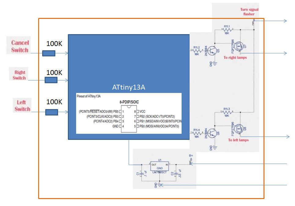
This is what it would look like with a micro controller. I did not quite follow the output drivers so it might be simplified as well. I don't really see the need for the trannys for a micro-controller.Originally posted by rustybronco View Post
Comment
-
Unfortunately I didn't feel like sitting down trying to wrap my head around coding a micro controller. Maybe someday when I have the time I will. I've had wallowgreens's (Martin) diagram, artwork and code for two years now, then there is Robert Barr's pic solution so here I am cranking on what I know, a hardware based solution.
Last edited by rustybronco; 04-24-2014, 11:10 PM.Comment
-
If Martin used a small controller then that would be the easiest thing to reproduce. Assuming he has a working unit( he told me in the end he just did it for himself) then just reproducing they design would be easiest. Certainly would be easier to produce and test.Originally posted by rustybronco View PostComment

.png)
Comment