Announcement

Collapse
No announcement yet.

Schematic and guide to fit relays

Collapse
X
 
  • Filter
  • Time
  • Show
Clear All
new posts

    #16
    wow you have been busy Matchless!
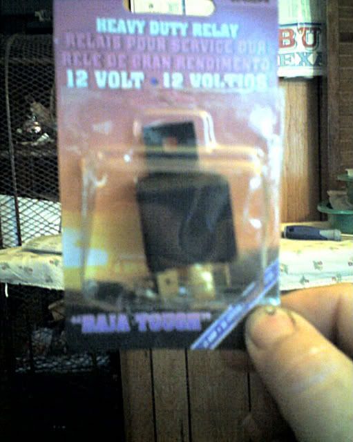
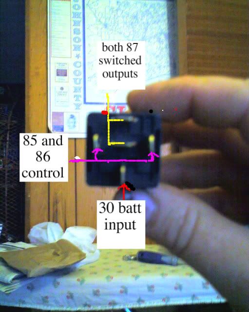
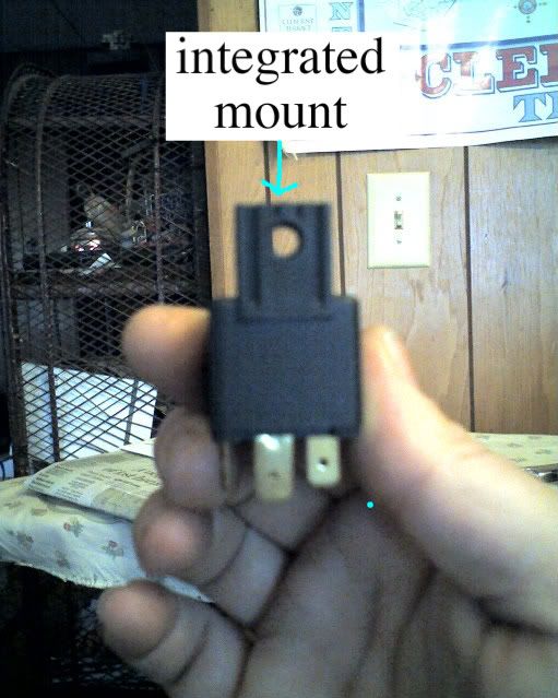
    a item I would like to add. it is very common for auto parts places to have a fog/driving light relay in close proximity to the electrical connectors and lights.
    this is a decent relay and it was made to be used in continuous operation (on all the time) it also has a mounting tab making it good for our purpose, but is is different from the standard generic VF4 type relay in that it has 5 terminals but instead of one being a 87A, it has two 87 terminals so two different items can be controlled from the one relay without splicing.

    these relays can't be used for the headlight cut out mod though.

    Comment


      #17
      I also went and picked up a relay and fuse holder to do the master ignition relay mod I had mentioned documenting earlyer but when I pulled the seat and side covers I discovered I have oldtimers and have already done it! (DOH!)

      so here is how it goes.

      this is a good all around mod and eliminates a healthy chunk of the voltage loss in all systems on a GS. unfortunatly this mod is desgned for the larger GS that have a full fuse panel. smaller GS often have just one fuse, the master fuse, a cost saving step Suzuki did that lieves them vunerable.

      earlyer glass tube fuse panel/ box have a pigtail, later models have the plug dirrectly connecting to the fuse panel with better blade type fuses.

      this plug has seven wires. two red, solid orange, orange with white stripe, orange with yellow stripe, orange with green stripe.

      first disconnect the ground from the battery, you don't want to let the smoke out the harness doing this mod.

      chose a location for the relay, I mounted mine to the frame tube that passes over the fuse box mounting panel.

      the inline fuse holder needs to be connected to the battery side of the starter solinoid and the other end connects to the 30 terminal of the relay.
      a ground leed runs from the 86 terminal on the relay to a good ground. as I have already done the ground mod for the R&R I just ran the ground to the starter solinoid mounting bracket screw.
      you now need to cut the solid orange wire that runs to the fuse box, this is the master power return from the ignition.

      Comment


        #18
        make sure to just cut the solid orange wire as there is three other orange wires but they have white, red, and green stripes.

        splice on enough wire to reach the relay and the one that comes from the fuse box connects to the 87 terminal on the relay and the one coming from the harness end connects to the 85 terminal on the realy.

        and you are done, nice and simple!

        Comment


          #19
          Originally posted by Matchless View Post
          I have just once again updated the version. Some photos of the material required added, an error in the schematic fixed and a few more changes.
          The first post has the latest link.
          Hope it helps someone.
          it sure does, matchless!
          i'm in the phase of "study" of your writing and plan on embarking on the coils and headlight relay upgrade as soon as i get my head around the background #theory#
          [-o<

          cheers

          ps. interesting to learn you have "Opel" in SA, much like in Europe, but unlike here in NZ (or AUS) where they are called "Holden"
          GS850GT

          Comment


            #20
            psyguy,
            Glad to know that it is of interest. Let me know if anything is not clear as the writeup is more sort of generic and the schematic is really what you have to follow.
            I recently built a control box for our clay target trench machine that interfaces to the scrambler and the 5 traps, using the 5 pin relays and various other parts and all runs off a 12volt battery. The only problem to date has been the glass fuses and I think we should seriously start replacing the fuse holders with blade type fuses on our bikes. These are very old technology and not used in vehicle manufacturing anymore because of their unreliability and tendency to make bad contact.

            Yes we have Opel here, in actual fact it is marketed as Vauxhall in the UK, my daughter has an Opel Corsa and I have an Opel Astra and a Opel Corsa ldv.


            Focus frenzy,
            Thanks for the tip on the double output relays, I am going to try and find some here for a picture and will then add a small schematic to help with connecting up.

            Comment


              #21
              Originally posted by Matchless View Post
              Yes we have Opel here, in actual fact it is marketed as Vauxhall in the UK, my daughter has an Opel Corsa and I have an Opel Astra and a Opel Corsa ldv.
              when i was in europe a couple of years ago, i had an Astra myself (the new one), 1.6 petrol engine and tiptronic 5speed auto gearbox
              i really loved the car, especially the gearbox was soooo smart! :-D
              GS850GT

              Comment


                #22
                Originally posted by Matchless View Post
                Focus frenzy,
                Thanks for the tip on the double output relays, I am going to try and find some here for a picture and will then add a small schematic to help with connecting up.
                it is marketed by tiger accessory group, and the blister package is marked "baja tough" but I have seen the marked as "blazer"

                here are a couple pictures.


                Comment


                  #23
                  what the &*%$#? those should be page size and have little text boxes and arrows?

                  Comment


                    #24
                    Relay Mods

                    Thanks Guys,
                    These mods are so sensible and not really too difficult to do.
                    I already used one relay to switch the R/R sense wire out of the pos. battery circuit when the bike is switched off. It is mounted to the right of the battery box because it is powered off the brake light circuit. I have the relays ready to go except for the five prong and It will be next. It is so nice of you to share.
                    Lee :-D

                    Comment


                      #25
                      just wondering, are these relays water-proof?
                      i dont think theres enough room in my headlight bucket to fit something of that size
                      GS850GT

                      Comment


                        #26
                        Originally posted by psyguy View Post
                        just wondering, are these relays water-proof?
                        i dont think theres enough room in my headlight bucket to fit something of that size
                        well there are water proof versions made, but most all of them are water resistant, you mount them upright with the contacts pointed down it is very dificult for water to get in them.

                        I have ridden in the rain many times and yet to have a problem.

                        for the headlight bucket you need to get a mini relay.
                        you can get one by asking your auto parts place for a fog light, or headlight relay for a ford focus. (2001) they are half as wide as a regular one and are rated for the same load. you can also run the wiring outside the bucket to a spot under the tank.

                        I only have the headlight cut out relay in the bucket.
                        the high low control relay is located under the tank in the space above the coils.
                        the other relays sit under the left side cover.

                        Comment


                          #27
                          Focus,
                          Thanks for your input. I have managed to get a 5 pin with a double 87 output and have once again updated the schematic in the guide. Yes, installing with the pins down is the correct way to keep water out.
                          If anyone can post a picture of where they mounted the relays it would help others. The biggest issue here is space.
                          Miniature relays are also available from electronics supply stores for 12volt, but the current handling of the contacts is important and must exceed the amperage you are switching, a 60W headlamp draws 5 Amp, so any 10 Amp 12 volt relay should in theory do as well.
                          I will keep updating the guide as more information is forthcoming from any of you. The idea is to then just add the schematic to your wiring diagram to show the modification or modifications done in case some fault finding takes place later on and you have forgotten what was done before.

                          Comment


                            #28
                            Originally posted by Matchless View Post
                            Miniature relays are also available from electronics supply stores for 12volt, but the current handling of the contacts is important and must exceed the amperage you are switching, a 60W headlamp draws 5 Amp, so any 10 Amp 12 volt relay should in theory do as well.
                            i'm wanting to go ahead with this mod, but the elctrics are not my strong side...
                            so, what exactly do i ask for at the electronics supply store?
                            a "10amp 12volt relay"? is that what they re called?

                            if someone could have a look at the link and make a suggestion, that'd be great :-D
                            Last edited by psyguy; 03-30-2008, 06:06 AM.
                            GS850GT

                            Comment


                              #29
                              Just for info here is a link that gives an easy overview on the relays. http://www.6066gmcguy.org/BoschRelay.htm

                              Just for clarity two types of relay can be used, a change over contact (usually 5 pin) or a make contact (usually 4 pin). The change over contact can be used in place of the make and the 3rd contact is just left unwired, but the make contact cannot be used in the change over relays place.

                              To keep it simple at an electronics shop, just ask for a Relay 12volt, 10A or 15 amp with a change over contact. The change over contact is then able to switch on or off when operating the relay. Those available from the electronics shop will require soldering leads to the pins. Only consider these if you can get smaller than the automotive one and do not have space for the one below.

                              Bosch automotive types are 25mm x 25mm x 25mm from the automotive store without the mounting lug, which is useful, but can be cut off if space is a problem and also without the pin protusions that are about10mm, but get longer with a lug and larger with a plugin base. Buy the 5 pin with pins 85, 86, 30, 87, 87a as these are change over. See my picture in the guide. If you ask them for a 12v horn or foglight relay you will most likely get the 4 pin that is only a make contact which is useful for all the mods except the headlight mod (not the starter, disable headlight mod) which requires a change over.

                              Comment


                                #30
                                Looking at the Bosch relays, there are may variations and maybe someone could help with the Bosch part numbers as stamped on the relays. These may a bit, but cannot conform that they are correct:
                                0 332 019 150 SPST (NO) 5 pin 87+87 Bracket mount (Confirmed)
                                0 332 019 151 SPDT (NO) 5 pin 87+87 No Bracket
                                0 332 209 150 SPDT (CO) 5 pin 87+87a Bracket mount
                                0 332 209 151 SPDT (CO) 5 pin 87+87a No bracket
                                0 332 017 302 SPST (NO) 4 pin 87 micro Bracket mount
                                0 332 207 307 SPST (NO) 4 pin 87 micro No bracket
                                0 332 019 110 SPST (NO) 4 pin 87 Bracket

                                It seems like their are 100's of equivalents and numbers that have been replaced by others and also other equivalent makes.

                                Comment

                                Working...
                                X