Announcement

Collapse
No announcement yet.

Degreeing Camshafts -- Information Required

Collapse
X
 
  • Filter
  • Time
  • Show
Clear All
new posts

    Degreeing Camshafts -- Information Required

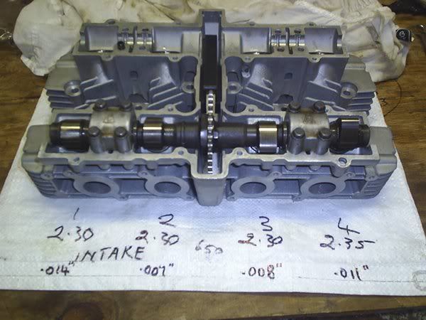
    I have the new 650 cams and sprockets on their way from the U.S. As soon as I have the valve stems ground to size and the cams arrive I will be going ahead and degreeing them with YOUR help.

    There's not much on the GSR forum about degreeing cams on the 8 Valve motors that I could find.

    All that I have read refers to having the dial gauge probe set up on the bucket to record the crankshaft movement in relation to the degree wheel. But how do you fit the dial gauge so the probe is on the bucket. In the pics that will be included below it will be seen that the bucket is not visible from above when the cam lobe is rotating. How can the probe go on the bucket if the lobe is in the way.

    Any suggestions greatfully appreciated.


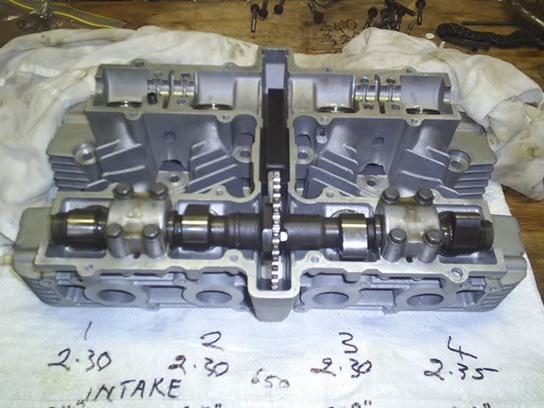
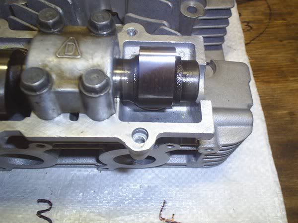
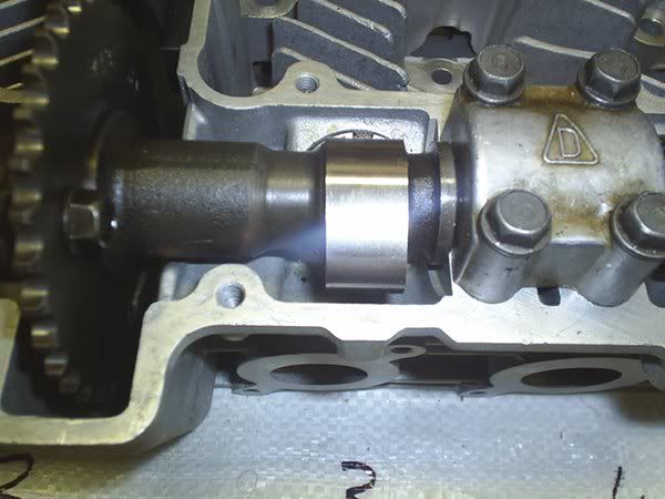
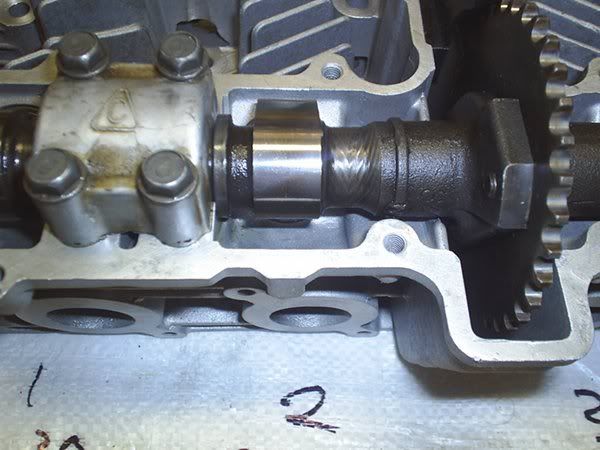
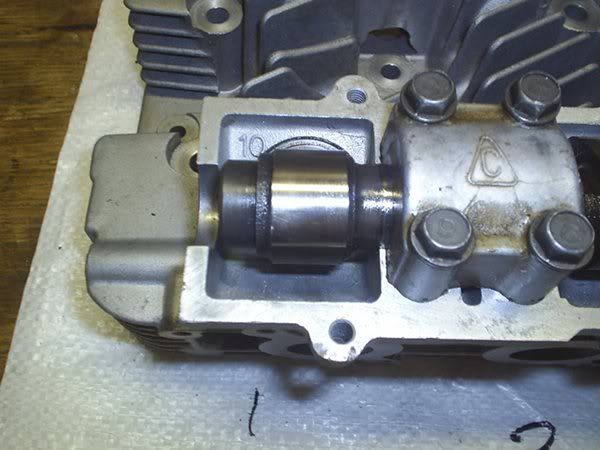
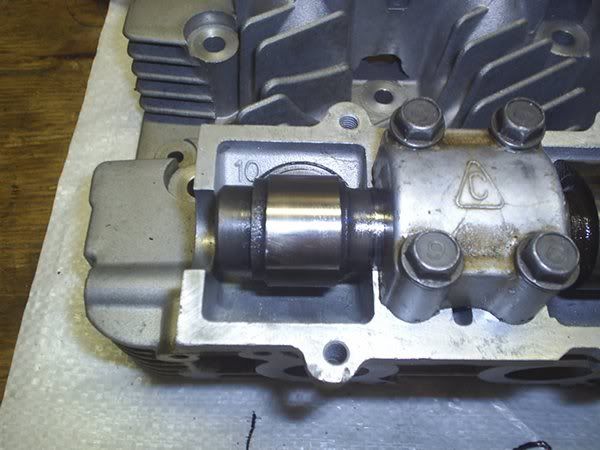
    Can anyone see how to mount the dial gauge probe on the bucket with cam lobe in the way.

    Thanks.
    Last edited by Guest; 03-03-2010, 06:14 PM.

    #2
    I've never degreed a 2 valve before, I would imagine that you could run the dial indicator right on the lobe, in-line with the valve angle. When I degree mine with the engine installed I mount the mag mount on the frame above the head, with the engine out, fashion a piece of flat steel to bolt to two of the valve cover bolts.
    On the web cams website http://www.webcamshafts.com/ there is a page to help you calculate your intake and exhaust centerline.

    Comment


      #3
      I know how to take opening and closing figures and determine the centreline for a given camshaft. The problem for me lies in the practicalities of mounting the dial gauge to obtain the opening and closing degree readings at a given reading on the dial gauge (0.040" or 1mm).

      If I was to mount the probe on the cam lobe itself I don't think that would work. The measurement needs to be taken as the valve is opening and if the lobe is facing towards you as you take the reading then everything is in reverse and not taking the reading that you require. Unless I am misunderstanding you.

      Any other ideas. If I have misunderstood then please correct me.

      Comment


        #4
        Originally posted by Suzuki_Don View Post
        I know how to take opening and closing figures and determine the centreline for a given camshaft. The problem for me lies in the practicalities of mounting the dial gauge to obtain the opening and closing degree readings at a given reading on the dial gauge (0.040" or 1mm).

        If I was to mount the probe on the cam lobe itself I don't think that would work. The measurement needs to be taken as the valve is opening and if the lobe is facing towards you as you take the reading then everything is in reverse and not taking the reading that you require. Unless I am misunderstanding you.

        Any other ideas. If I have misunderstood then please correct me.
        Ok, ya I had a brain fart about putting the indicator on top of the lobe
        I thought someone that had done this before would have chimed in by now. Has to be some way of doing it.....

        Comment


          #5
          Originally posted by gearhead13 View Post
          Ok, ya I had a brain fart about putting the indicator on top of the lobe
          I thought someone that had done this before would have chimed in by now. Has to be some way of doing it.....
          I guess no-one has done it before.

          I had a thought that instead of using a dial gauge to use a feeler gauge instead. Fit a much thinner shim to allow say a .035" feeler gauge (maybe .035 is a bit thick) between lobe and shim. When the lobe contacts the feeler gauge take a reading in degrees off the degree wheel. And do the same as the lobe is coming off the feeler gauge.

          Or maybe use as thick a feeler gauge as possible and allow the dial gauge probe to rest on the feeler gauge where it extends beyond the bucket, then as the lobe depresses the feeler and shim/bucket the dial gauge will also give a reading off the top side of the feeler gauge.

          What do you think.
          Last edited by Guest; 03-03-2010, 03:34 PM.

          Comment


            #6
            I'd PM trippivot. He use to or does dragrace eight valve motors.
            I betcha he's degreed in a few cams for them.
            1983 GS 1100E w/ 1230 kit, .340 lift Web Cams, Ape heavy duty valve springs, 83 1100 head with 1.5mm oversized SS intake valves, 1150 crank, Vance and Hines 1150 SuperHub, Star Racing high volume oil pump gears, 36mm carebs Dynojet stage 3 jet kit, Posplayr's SSPB, Progressive rear shocks and fork springs, Dyna 2000, Dynatek green coils and Vance & Hines 4-1 exhaust.
            1985 GS1150ES stock with 85 Red E bodywork.

            Comment


              #7
              Thanks Bill. I'll give that a try.

              Comment


                #8
                Just a curiosity from me,since i own a 650, what happen to the exaust cam? Is there something i should worries about?

                Thanks André

                Comment


                  #9
                  Use an end lobe - there's just enough room to get a DTI with an extended tip onto the shim - or the edge of the bucket - where the cam end reduces in diameter.
                  You can never get it directly in line with the valve angle but it's close enough if you use a reasonable point in the lift to take your figures - I use .o40in lift for all my work.
                  The method I suggested earlier using a thin shim and a feeler gauge is accurate enough if you don't have access to a DTI.

                  Added for Andre - the exhaust is closing till well after TDC so clearance to the piston here is even more important than on the inlet as any valve bounce or a retarded cam spells much $$$$ if valve hits piston

                  Greg T
                  Last edited by GregT; 03-03-2010, 06:03 PM.

                  Comment


                    #10
                    Originally posted by GregT View Post
                    Use an end lobe - there's just enough room to get a DTI with an extended tip onto the shim - or the edge of the bucket - where the cam end reduces in diameter.
                    You can never get it directly in line with the valve angle but it's close enough if you use a reasonable point in the lift to take your figures - I use .o40in lift for all my work.
                    The method I suggested earlier using a thin shim and a feeler gauge is accurate enough if you don't have access to a DTI.

                    Greg T
                    Thanks Greg your info is very helpful.

                    I will check out the cam and head when I get home to look at the things you have mentioned.

                    Thanx again.

                    Comment


                      #11
                      Originally posted by André View Post
                      Just a curiosity from me,since i own a 650, what happen to the exaust cam? Is there something i should worries about?
                      Thanks André
                      Hi Andre, the problem with my exhaust cam was the tacho drive skew gear was chewed up. Apart from that the cam was fine. No wear on the lobes or bearing journals. Just would not have had a tacho that worked. The tacho drives off the exhaust cam on the 8 valve motors.

                      Comment


                        #12
                        Cut your cam end off.

                        kz and gs 2 valves you have to cut the little end off leaving the side of the lobe smooth.

                        your dial probe can be set up on the bucket just to the side of #4 cam lobe with out obstruction.

                        I like to trim the right side#4 but #1 will work too. REMEMBER You do not want to turn the engine with the same nut as the degree wheel is on.

                        I have a cool set up where I read the wheel in a mirror while looking at my dial indicator.

                        a rock style chop saw and chop right after the #4 lobes int and exh --smooth-- any little puck left will hit your probe. because you need the probe perfect in line (parallell and perpendictular) with the bucket movement. and if you get it smooth you will have juuuust enough space for the probe. do not worry about the heat treating and such. I've done this to hundreds of customers motorcycles. I do not usually let them witness the cutting. just the degreeing and writing down the numbers.

                        I should get paid for this forbidden knowledge. but I like you guys.
                        SUZUKI , There is no substitute

                        Comment


                          #13
                          THANKS TRIPPIVOT.

                          Great information. Do you have any pictures by any chance.

                          Still waiting on camshafts to arrive. Put the oil pump, clutch and gearshift mechanism in last nite. Not in that order though.

                          Comment


                            #14
                            Thanks for your reply,the more I learn the best it is.

                            Good luck and happy rides.

                            André

                            Comment


                              #15
                              Originally posted by trippivot View Post
                              kz and gs 2 valves you have to cut the little end off leaving the side of the lobe smooth.

                              your dial probe can be set up on the bucket just to the side of #4 cam lobe with out obstruction.

                              I like to trim the right side#4 but #1 will work too. REMEMBER You do not want to turn the engine with the same nut as the degree wheel is on.

                              I have a cool set up where I read the wheel in a mirror while looking at my dial indicator.

                              a rock style chop saw and chop right after the #4 lobes int and exh --smooth-- any little puck left will hit your probe. because you need the probe perfect in line (parallell and perpendictular) with the bucket movement. and if you get it smooth you will have juuuust enough space for the probe. do not worry about the heat treating and such. I've done this to hundreds of customers motorcycles. I do not usually let them witness the cutting. just the degreeing and writing down the numbers.

                              I should get paid for this forbidden knowledge. but I like you guys.
                              Ummm, I have to chop the ends of my cams off?
                              I have an 83 GPz 750 (well, it's an 810 now with the Wiseco kit) and I have milled the head, so I have to degree the camshafts. It's an 8 valve shim-under-bucket KZ-based motor, so it should be the same as a GS. The sprockets have been slotted, so it is ready to be degreed. I have a magnetic dial gauge, and a degree wheel. I also have the technical expertise to do the work once everything is in place.
                              Suzuki_Don, have you done this yet? I am really freaked about having my camshaft ends removed. I'll have to take them to a shop, since I don't own a chop saw nor do I have the intestinal fortitude to watch it being done. I take it the other 3 bearings support the camshaft enough to prevent any flexing. Redline on this engine is 10k and it is a street-legal twistie-capable machine.

                              Comment

                              Working...
                              X