Announcement

Collapse
No announcement yet.

'77 GS750 rebuild... continuation

Collapse
X
 
  • Filter
  • Time
  • Show
Clear All
new posts

    #16
    Originally posted by Druid View Post
    I might be able to help with the brake caliper. I have a lhs caliper from a 77 GS750. I'm fitting GSXR1100 forks and twin discs to mine so assuming the caliper is the same as yours and it's the right side I'll sell it to you.


    Looks like it's been recently refurbished, even has a new brake line.
    Thanks mate - but I've just finished tearing em apart and rebuilding - both front and rear working now, with braided lines an' all. not exactly spick 'n' span yet, I'll have to pull apart again and put in a new piston kit on one and master needs repair kit (both on order), but a good practice run and functional enough for SORN bike.

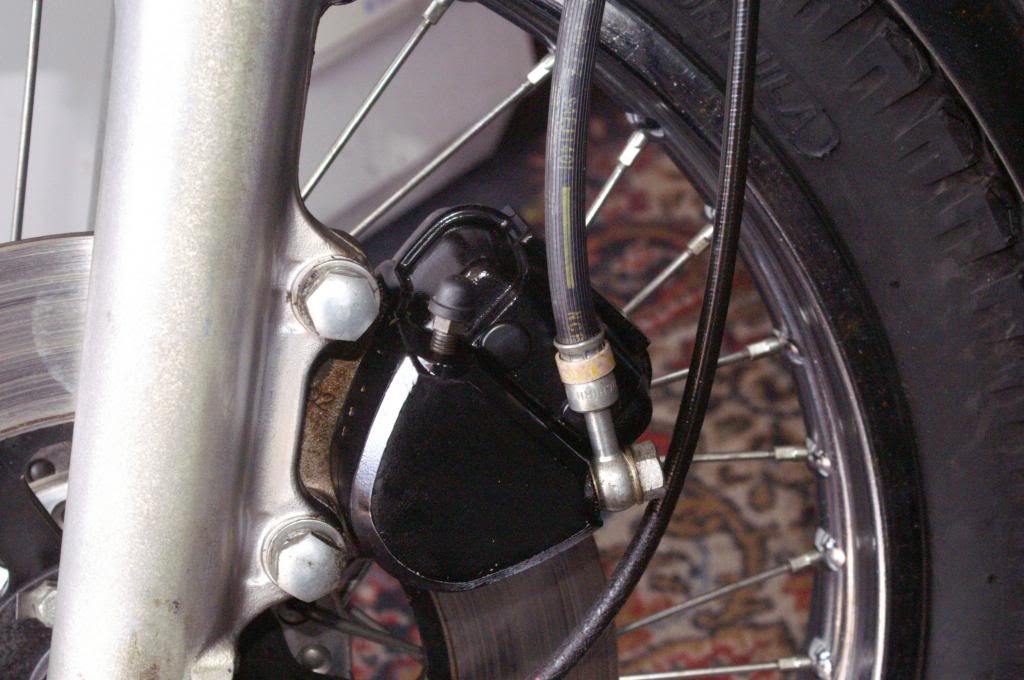
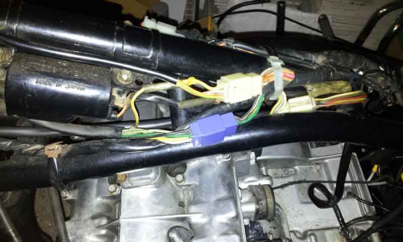
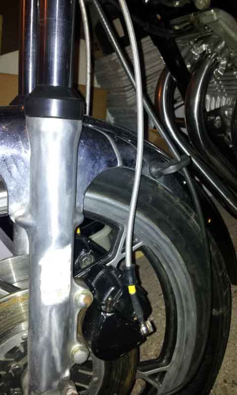
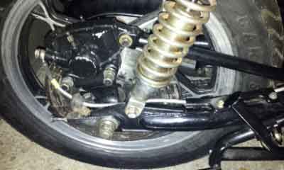
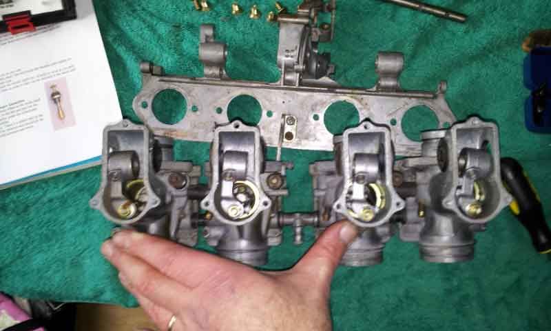
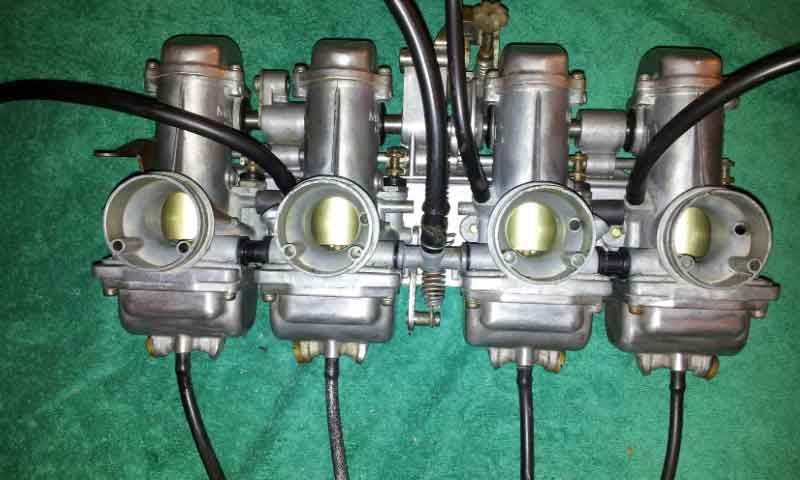
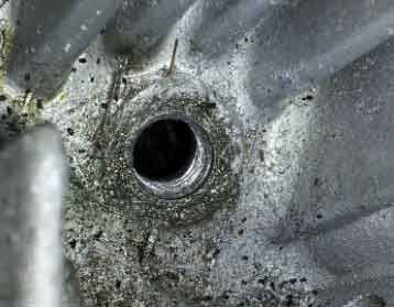
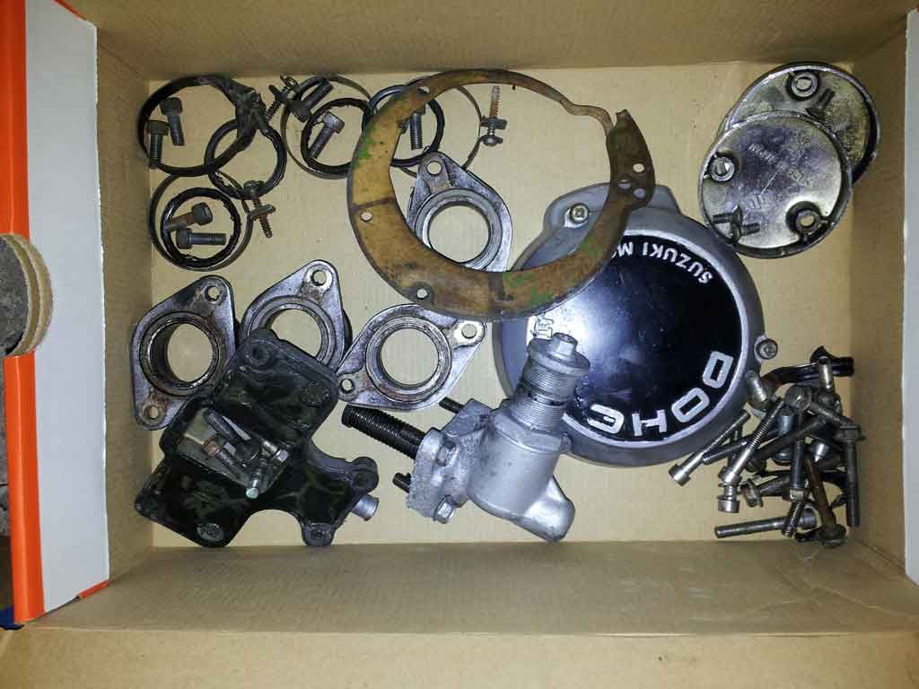
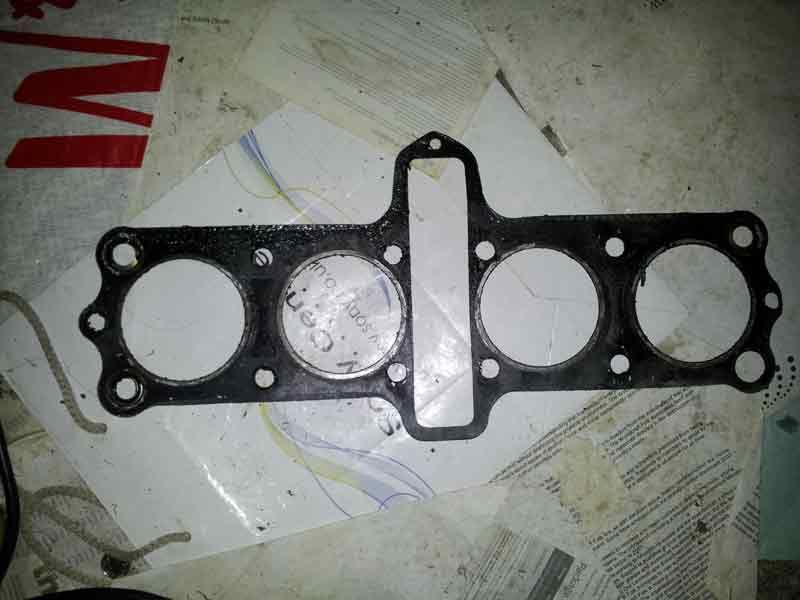
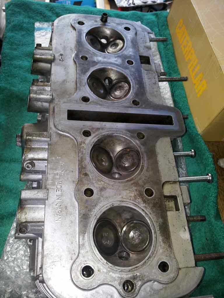
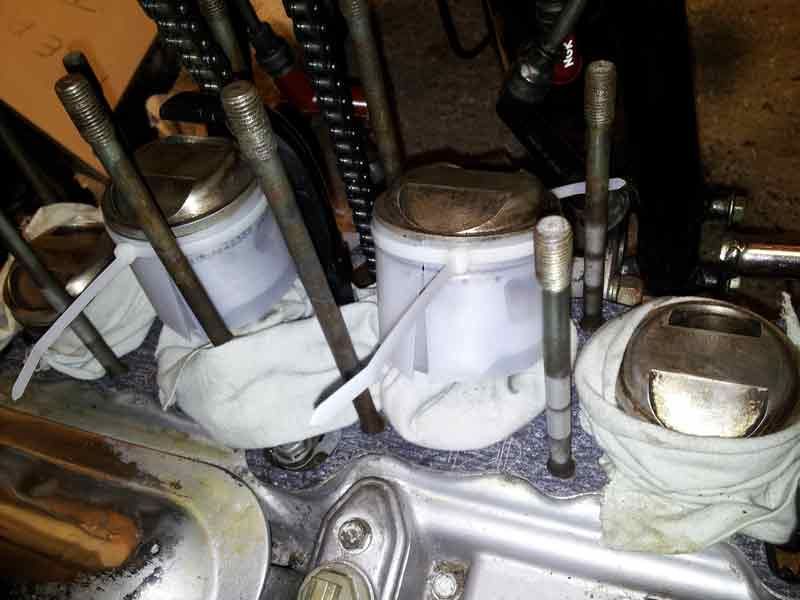
    So anyway - that was pretty much what I did this weekend, finished off cleaning up previously seized brakes (calipers and masters) an put them back together. Yay me! Oh, and I figured out some wiring crap and persuaded everything to work barring horn and front brake light switch (on order as well).

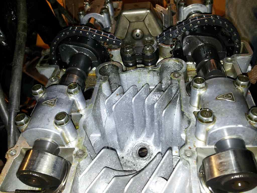
    I'm one step closer to figuring out what's from where I think, tanks to wiring diagrams. The only one that seems to fit the loom (and therefore I think switchgear as they share unique junctions) is the GS750E(Z) one. I've not checked everything on it, but the switchgear junction and the fusebox are same, but different to other wiring diagrams on BikeCliff's page. I'm thinking then that most of front end is probably a US E (dual disks, alloy rims, no light switch etc) and that the loom has come with it onto the '77 frame and engine. O' course it may still be a broader mash up of bikes, I'm sure I'll continue to be surprised.

    Getting there tho. Feels a whole lot better when you can start putting stuff back together

    Oh, and Gatekeeper - good point, the chrome headlight is a lot more obvious than I thought in that pic

    Comment


      #17
      brake light switch wiring

      So, I had two little problems left in terms of wiring; horn and front brake light switch. Tonight I managed to trace the horn problem back to the switchgear - opened it up and removed the spiders nest (literally, a spiders nest) from inside and persuaded the very meek sounding horn to beep.

      Other problem was where will the front brake light switch connect to? (when a replacement arrives). I think I've half tracked down the answer on these forums reading between the lines... somewhere in the huge bundle of wiring crammed in behind the headlight. If anyone knows different please tell me before I risk all and start dismantling to get at the connectors I hope I will find there. As I said before, I'm pretty convinced its a 750E loom...

      Also, this site is awesome! Partly cos there are so many nice people offering to help out, and answers to almost any question to be found by searching and interpreting, but most of all for inspiration . Flushed with my success so far I'm becoming more determined to do a full top end overhaul in time, and hopefully eventually get her running like new some day. Meantime, so glad I started out on this adventure.

      Comment


        #18
        The brake light switch does usually hook up in the big bundle inside the headlight. Luckily, the wires are all color coded and all you have to do is find the right colors. This is where wiring diagrams come in so very handy.

        For the 750s, the 16-valve has the front brake light switch as orange with a green tracer on one side and white on the other. The 8-valve bikes have simply orange and white wires with no tracer colors.

        Comment


          #19
          Thanks Griffyn, sound's like it's exactly as I thought. The wiring so far matches up to the 16-valve bike I think (though the engine and frame are 8-valve). But because the bike came without any fr brake light switch and wiring diagrams don't show where connectors are actually located, I was left wondering if I was failing to find the connectors under the tank where other switchgear connectors seem to sit, or whether they were indeed stuffed behind headlight. Looks like tonight's job will involve headlight removal in order to examine the nest behind.
          But like I said, thanks very much for the informed advice

          edit: I opened up nest inside headlight last night, unravelled a bit and found the two connectors - orange/green and white
          Last edited by Guest; 12-18-2013, 10:46 AM. Reason: minor update

          Comment


            #20
            Christmas update #1

            OK, so it's been a little while since I posted, so I thought it was about time I updated. Problem is I keep failing to take pictures, so I've kind of done a few "after"s without very many "before"s - better than nothing I guess though
            So first off, an illustration of why I've drawn my conclusions regarding the wiring... All this really shows of any note is the blue connector from LH switchgear...

            there's also the fuse box wiring which I don't have a pic of.
            I think I may have also mentioned that I had stripped down and unseized both front and back brakes - sorry, no photo's of the process, but here's a couple of after pictures, with new braided hoses fitted. I was waiting for full master cylinder repair kit from the US which quoted shipping times up to 10 weeks, so I put the front together with original parts... It works, but lever is rather sluggish to return (dodgy cup / MC piston I think), so I'll be draining and rebuilding again when parts arrive - this time I'll take a picture of it stripped down.


            By the way, weird photo, my rear shocks are not gold.
            This project often seems like it's three steps forward, two back - for every little thing I fix, I seem to find something new wrong. I mention that because whilst fitting the drive chain, I decided to check swingarm bearing condition... only to find a complete absence of bearings (spacers yes, bearings no). New parts on order now, along with missing frame engine plate. Problem is still that I have to keep checking exploded diagrams just to figure out whether there's something missing and if so what - makes me nervous! Just gonna have to check everything I guess.
            Next post on carb stripdown... Cheers

            Comment


              #21
              Christmas update #2

              Almost up to date now - I spent all day yesterday stripping down the carbs, very carefully following instructions from Paul Musser's VM carb rebuild PDF... Except for the bit about having all the O Rings ready... They're on order and I'll strip again and finish the job when they get here, at least I got the cleaning and turn counting part done. Here's a before:-

              (notice the printed copy of pdf top right), and an interior shot (sorry for blur):-

              and here's the after:-

              ...They're not spotless - I couldn't find any suitable carb-dip in UK, so went for carb cleaner spray and scrubbing - but they're hopefully clean enough to be functional.
              One thing, none of the pilot air screws started out lining up with their factory notches, so I guess some PO has messed with them. Not knowing where the factory setting would be I've returned them to the settings I found them at - I guess I'm gonna have to work my way through the tuning part when she's running again (...if...)
              Another headache emerged during the strip down of carbs - all but one of the little choke levers (screwed onto choke shaft) have snapped. I can't find replacements anywhere, does anyone out there have any suggestions?
              At the moment I think I may have to resort to fabricating something with 13 guage (coat hanger) wire or aluminium sheet (empty beer cans).
              Would these

              (from a 79 model) fit? I'm guessing so since they seem to go on VM carbs and simply be a better design. (photo is from an ended ebay item)
              I guess I also have to keep my fingers crossed that the fuel connector moulded o rings remain up to the job.

              Anyway, enough for now, Cheers, Merry Christmas and Happy New Year!
              Tom

              Comment


                #22
                choke lever things

                So, big shout out to uk gs nut, who's not only sourced the choke lever replacements from his private stash, but has posted them off to me quicker than most suppliers would manage. A true gentleman.

                Also over Christmas I met up with a mate's Dad who it turns out has had a GS in the past. I was hoping to get to chat to him a bit more, but it was a 1st birthday party for his grandson so he was a bit tied up. However, he did bring a couple of useful items for me to borrow; a compression tester and a carb balancer (just needs new rubber tubes and their fastenings). I started to set up for compression test and realised #3 plug was not screwed in properly - tight, but not seated - badly crossed threads


                I ran the compression test on #1 #2 and #4 and got around 130psi on #2 and #4, but a very limp 90-100 on #1. Shining a torch down the plug holes all but #1 piston tops look fairly clean, but #1 is black as soot. I'm hoping that the low compression is due to build up of carbon making for a bad valve seal. Time to man up and take the heads off, clean and check everything and check/grind valves etc.
                Extra tools required for this are now on the way, including a tap/helicoil kit for the plug thread.

                I dropped the sump last night to get at the oil strainer (engine still in frame as service manual suggests is possible). Problem is I now have to try to get a nice clean blow on impact driver to unscrew the strainer - from underneath the bike! I think I am going to either a) leave the bloody thing where it is and just wipe down the visible side or b) lean the bike over against garage wall using my son as a cushion/support, to try and get a good angle on impact driver... Hmmm

                Comment


                  #23
                  77 gs750 rebuild

                  Tom, i posted before 12 noon so you should have them soon.
                  My bikes 79 GS1000 1085 checked and approved by stator the GSR mascot and 77 GS750 with 850 top end, GS850g, and my eldest sons 78 GS550, youngest sons GS125. Project bike 79 GS1000N
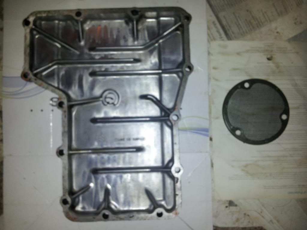
                  Comment


                    #24
                    sump and strainer

                    First off, you the man Dennis, you the man. Thank you so much

                    Second, thought I'd do a quick post on activities today. I figured I had to do the sump and oil strainer thing right, so got my son to help gently lower bike almost onto it's side - he's only 14, but 6' 1" and a rugby player. Once we had it leaning on him and some regular garage crap (camping gear etc) I was able to get in underneath with the impact driver and successfully undo the strainer screws.
                    Half a roll of kitchen towel later and some some careful brushing of the strainer and all the sludge is gone from sump along with any signs of swarf etc on the strainer.

                    Sorry - as usual hands were too dirty to take a before picture, but after draining oil there was still a thick layer of oil sludge stuck to the bottom of sump.

                    At the moment, unless I decide to put lighter clutch springs in (clutch seems very tough to me, certainly not a one finger job) I'm thinking that's the gearbox stuff done for now hopefully.

                    Comment


                      #25
                      Carbs finished & cylinder head off

                      So a couple of weeks ago I received my o-ring set from Robert Barr in the US, along with the intake o-rings I also needed. I set about replacing them all - including the float bowl drain screws which I had previously left untouched... Bad idea - the reason I'd left them was that they were very stiff, in fact glued into place with fuel deposits, and the second one I tried sheared off at the weak spot where it has a small hole drilled through to drain. The remains of the screw were still glued tight, so the only option was to very...very carefully drill out the brass and try to leave the thread in tact. Two hours later and I was able to screw the only other drain screw I had loosened into it with o-ring in place, nice and tight. Phew. Ordered a new drain screw to replace the sheared one, and decided I would have to leave the other two glued in place and just clean around them.

                      Carbs are now fully rebuilt and waiting to go on. My only worry is how well the fuel connector pipes will seal as there's no way to replace the o-rings on my type.

                      While I was waiting for carb parts, I also made a start on the cylinder head, having noticed a slight lack of compression and knowing I needed to do a re-tap / helicoil on one of the plug threads.
                      Carefully following Haynes instructions, I stripped down to cam covers - all parts basically needing a clean/o-ring/gasket replace. Check out the state of the intake o-rings for example (top left)


                      The cam cover gasket was noticeable only by its absence, being sealed with some form of (now hardened) liquid gasket which would need careful removal


                      After careful removal of cylinder head it turned out the pistons and head were not too dirty, showing signs of having been stripped and cleaned at some point by a previous owner... BUT...


                      This is not how a cylinder head gasket should look. Also, what you can't see is the amount of gooey liquid gasket type stuff all over it and the alloy on either side of it. Nice new head gasket bought (NOS as I was advised against aftermarket for the head gasket) and a long slow gasket scrape / head clean undertaken. After several hours of cleaning and polishing this was the best I could get.


                      The dark areas are completely smooth to the touch and show no visible lumps or bumps in reflection, so while it's not as shiney as might be possible, I think it should be up to a good working standard.

                      Since then I've put the head back on and am now working on shims... but that's another story.

                      Comment


                        #26
                        If you get in a bind on those carb bowls, I've got a couple laying around. A friend of mine tells me he purchased (recently)some of the connecting tubes from Z-1 Enterprises. Don't know how true it is. Might want to check their site and e-mail them.

                        cg
                        sigpic
                        83 GS1100g
                        2006 Triumph Sprint ST 1050

                        Ohhhh!........Torque sweet Temptress.........always whispering.... a murmuring Siren

                        Comment


                          #27
                          thanks Charlie

                          If you get in a bind on those carb bowls, I've got a couple laying around. A friend of mine tells me he purchased (recently)some of the connecting tubes from Z-1 Enterprises. Don't know how true it is. Might want to check their site and e-mail them.
                          Thanks very much for the offer/source suggestion Charlie. Knowing that I was hoping to test out carbs this weekend I put off replying... anyway, so far so good I think, the only leak I've found so far is a slight weep around petcock which I was half expecting and have already ordered a new rubber seal for. I guess I need to keep an eye on things for a while, but fingers crossed, for now the carbs seem to be behaving.

                          I'll be uploading some more pics and updating thread again (on my progress and adventures over past couple of weeks) very soon.

                          Comment


                            #28
                            Doh! Nut dropped into crankcase, and timing chain setup

                            I thought I'd better be honest about this, despite my shame. A couple of weekends ago, despite having stuffed rags in all the right places through almost all of the cylinder head removal/replacement, I managed to drop a nut down the camchain slot. Doh.
                            You may well ask how I let this happen - briefly, here's my excuse. Having replaced the cylinder head I needed to slide the front camchain blade in, but it's long and straight, and the only path I could find for it was through the frame where the coils bolt on... So figured I'd just loosen off one of the coils to make room for the blade to slot in. Of course up to this point I'd been intending to slide the blade in so had removed rags from the camchain slot... but not replaced them while I undid the coil nut... oily fingers... oops. NOOOoooooo! not down there of all places.
                            Anyway. That was the point I resigned myself to taking the cylinder block off as well, and I'm kind of glad I did. The oil seals and gasket underneath were in a hideous state.
                            The resolution to the nut in crankcase issue is shown below - using a "Magnetix" magnet (they're really strong) taped to the end of some stiff wire. I had to use stiff wire, as anything bendy just resuted in the magnet instantly sticking to the nearest stud or whatever. It's shown here with captured nut on the end.


                            It worked like a dream in the end, but was the end result of about four hours messing about with vacuum cleaner, tubing, other magnet related inventions and so on. Phew. But I highly recommend the magnetix method if anyone finds themselves in a similar situation.

                            So back to the rebuild. I replaced base gasket and oil seals having cleaned up all mating surfaces and set about replacing the barrels. At this point my problem was that I have big stumpy fingers and despite an hour or so trying couldn't seem to get the piston rings compressed enough to slide into barrels.
                            I had of course scoured this site for what help I could find and was on the verge of buying special tool when having read the suggestion to use hose clamps I made these:-


                            It's basically a hose clamp with a piece of plastic milk bottle taped to the inside. My thinking was that the design of my hose clamps was not something I'd want wrapped around and scratching at the pistons. The milk bottle plastic is soft and very slippy - ideal for the job as it can be tightened round the piston enough to hold rings in place, then slides off as the barrels are lowered. I'm afraid I've only got a picture of an earlier (unsuccesful) version using cable ties, but trust me, the hose clamp method works really well with the plastic.


                            Cylinder barrel, head, camchain blades, and cams all went on smoothly this time round. Time to set up camchain timing. Here's what I understood from reading the manual:-
                            Line up T mark:


                            Align 1 arrow with top of cylinder head so that 2 arrow is vertical (with respect to cylinder head surface) and front of chain is tight. In this photo, it looks like front of ex cam has rolled very slightly clockwise just before pic was taken:


                            Then count twenty pins on chain, and engage 3 arrow mark with that pin:


                            Top sprocket is then fastened and cams are clamped so that the bearing caps (A B C & D) can be safely bolded down.
                            If anyone sees these photos and spots that I've done something wrong or misunderstood anything, Pleeease let me know. I'm pretty sure I got it all right though, cos the engine started and managed to tick over happily enough last weekend

                            Enough for now though.

                            Comment

                            Working...
                            X