Announcement

Collapse
No announcement yet.

Solid State Power Box STANDARD INSTALLATION

Collapse
X
 
  • Filter
  • Time
  • Show
Clear All
new posts

    Solid State Power Box STANDARD INSTALLATION

    Download a copy of the install guide. It is a 13 page pdf file.
    Preliminary SSPB Installation Manual

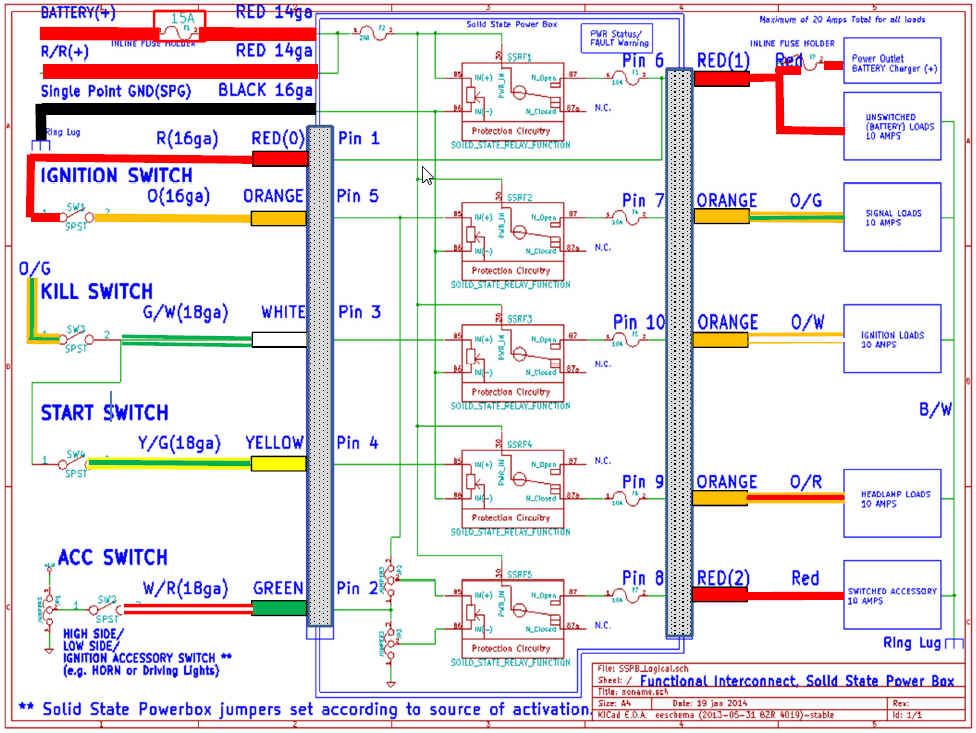
    This is a preliminary markup of a 1977 GS550 schematic and represents what is involved with converting your single fuse bike to use the SSPB.
    SSPB Install for 1977 GS550

    Status Update 1/17/2014
    The first 10 units of the Solid State Power Box with the Rev C PCB's (no red wires) have been completed and delivered. See this video and an overview of the capability and installation.
    SSPB Overview Video for First production units

    The first production run of the Solid State Power Box (SSPB) is in full swing now and I have been posting links to YouTube videos outlining standard installations of the SSPB.
    Solid State Power Box: 1983 GS1100 ED Demonstration


    Here is the original link describing the product.


    This thread will focus on Standard Installations for any GS Suzuki that already has a fuse box and you are looking to replace it with the SSPB. If you don't already have a fuse box and only have one main fuse, things are a little more complicated and I will start a new thread for describing that and others.


    Here is a small library of install videos for the SSPB.


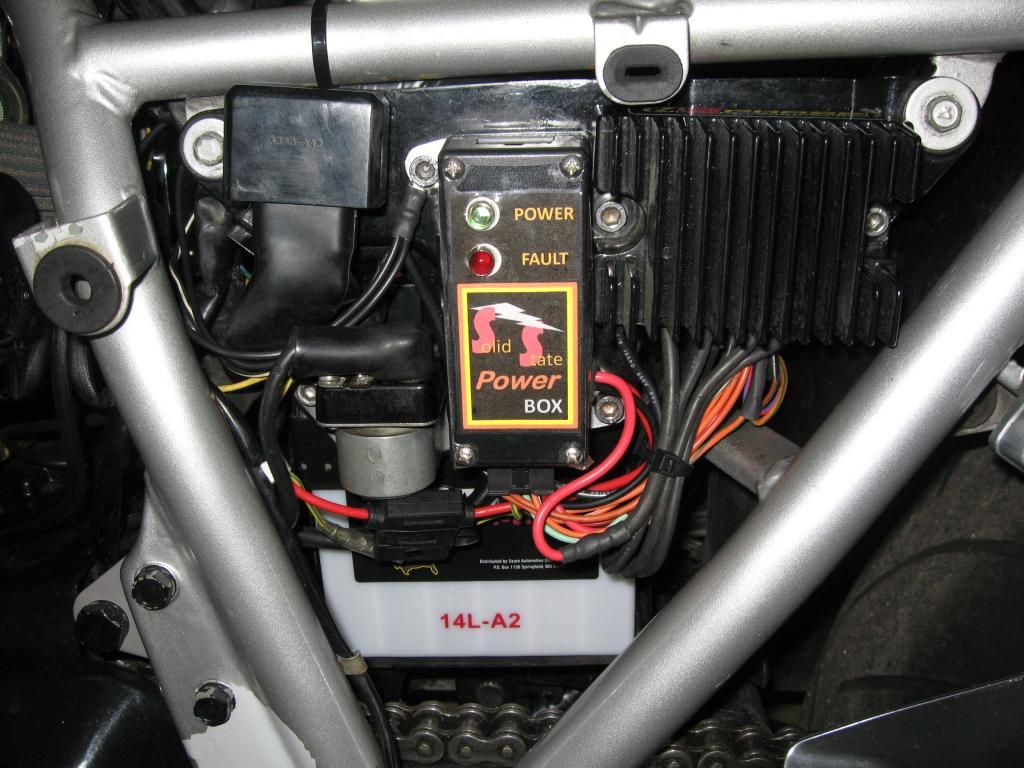
    Introduction to the Solid State Power Box (SSPB) features and capabilities. The SSPB replaces your existing motorcycle fusebox to upgrade and improve your entire motorcycle electrical system. The SSPB features five 10 amp, "Safe Power" channels for distribution to your harness. SSPB delivers power which is protected against over current, over temperature and +/- conducted voltage spikes. With the SSPB, the Ignition, Kill and Start switches only signal the SSPB to distribute power. This avoids voltage drops due to corroded and over heated switches and excessively long high current runs.
    Solid State Power Box Introduction


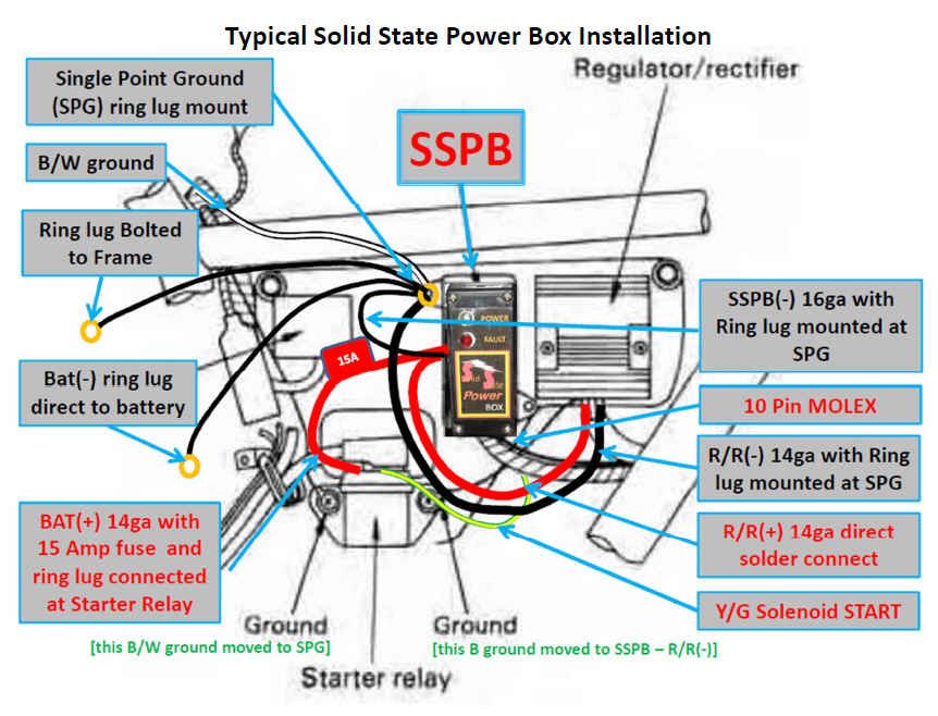
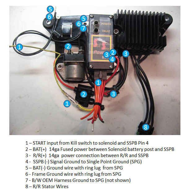
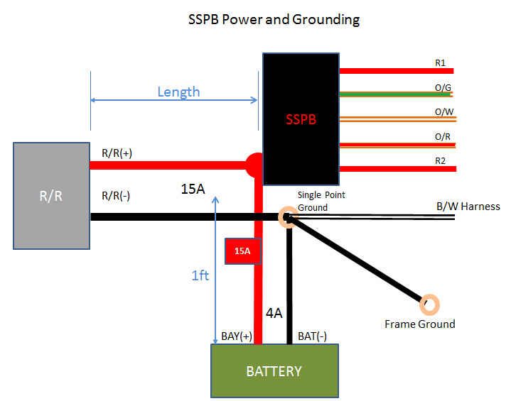
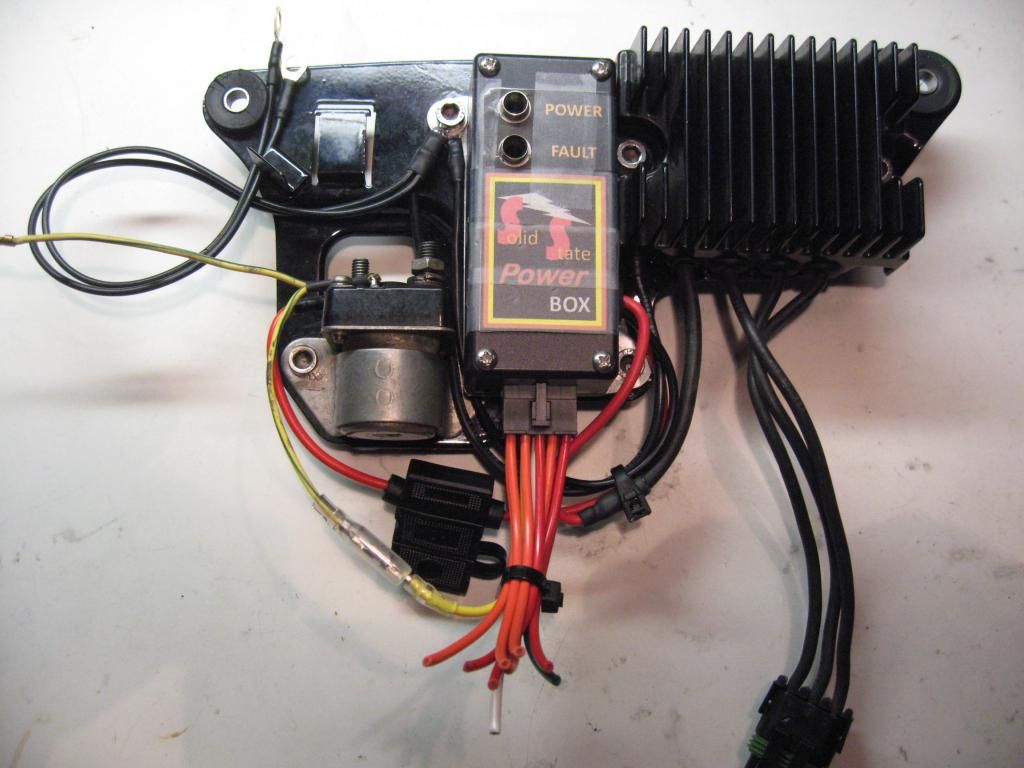
    Overview of interconnections for the Solid State Power Box and the installation on the electronics side plate of a 1983 GS1100ED with Compufire Series R/R. The install will be very similar for any 5 wire R/R. The video highlights the various connections made on the electronics side plate between the SSPB, R/R, Battery and starter solenoid including a Single Point Ground.
    #2 SolidStatePowerBox: Power and Ground Connections Part A

    #2 SolidStatePowerBox: Power and Ground Connections Part B


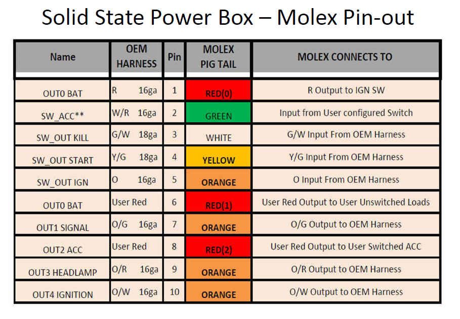
    Overview of interconnections for the Solid State Power Box and the GS Suzuki harness. Provides an overview of the Molex 10 pin connector pre-wired with pigtails and how to connect it to the harness.
    #3 SolidStatePowerBox: 10 Pin Molex Connectors Part A

    #3 SolidStatePowerBox: 10 Pin Molex Connectors Part B


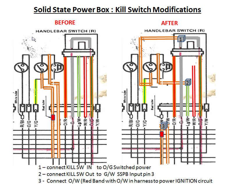
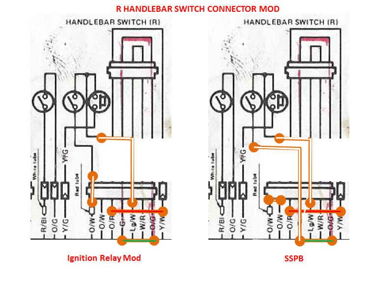
    Video showing the wiring and soldering techniques for attaching the MOLEX pigtail unit to your GS Suzuki harness. This applies to GS Suzuki's with stock fuse box with SIGNAL(O/G), HEADLAMP(O/R) and IGN(O/W) circuits.
    #4 SolidStatePowerBox: MOLEX/Pigtail to Harness Part A

    #4 SolidStatePowerBox: MOLEX/Pigtail to Harness Part B

    #4 SolidStatePowerBox: MOLEX/Pigtail to Harness Part C

    #4 SolidStatePowerBox: MOLEX/Pigtail to Harness Part D

    #4 SolidStatePowerBox: MOLEX/Pigtail to Harness Part E
    Last edited by posplayr; 01-21-2014, 08:56 PM.

    #2


    Kill Switch modifications are all done at the connector. Below is a picture with all three re connections. For the GS1100ED that is in the headlamp bucket.


    See additional consideration for modifications to the RH switch connections here


    Last edited by posplayr; 12-02-2015, 09:44 PM.

    Comment


      #3
      OPTIONS FOR VOLTMETER and POWER PORT INSTALLATION:

      Originally posted by greg78gs750 View Post
      picked up one of the earthquake proof ones. Does this wire right to the battery? maybe i could wire it into my sspb?
      Hook it to O/G (Pin7) SIGNAL or the RED2( Pin 8) switched ACCESSORY if you want the voltmeter only ON when the ignition switch is on. You would need t o jumper ACCESSORY to come on with the IGNITION SW however. If you use O/G, then keep it as close to the SSPB output as possible. If you converted to Led then probably any where on o/g.

      If you add a charger port then it is nice to see volts when trickle charging but you need an extra switch.
      I have an accessory port for 12v devices including trickle chargers. So I wanted to see voltage when the bike is off but not drain the batt. I measure the unswitched output at the plug but with a small inline switch I can turn off.

      it is not necessary to trickle charge , only to activate/deactivate the meter.

      Here is a schematic


      There are currently three heatsink options for mounting the SSPB to your bike.

      Diagonal tabbed base (fits later 1982+ GS models)

      Horizontal tabbed base (fits earlier version hole patterns)

      Tabless base for non standard installs where you want to save space.

      Last edited by posplayr; 05-14-2015, 03:20 PM.

      Comment


        #4
        INTRO
        Here is a little discussion on power and ground wire sizes and voltage drops between the R/R and Battery and what happens if you run 4 foot wires v.s. 1 foot in order to locate the R/R to the front of the bike. The SSPB is designed with relatively short 1 foot long leads. The R/R(+) and R/R(-) are 14ga while the BAT(-) is only 16ga. According to this analysis while charging you can expect just at 0.1V drop (between R/R and battery) due to the size of these cables. In other words there is really no reason to put in larger ones.

        DISCUSSION:
        There is no reason that you could not extend the Red R/R(+) wire and the Black R/R(-) wires 4 feet to put the R/R in the front of the bike. The SSPB would not care but you will lose voltage to the battery and it will not charge as much.

        I did some quick calculations (assuming standard ignition and incandescent bulb loads) and here are the results:

        This is the basic configuration for how the SSPB is connected to the battery and R/R. In this analysis I am going to change the length from 1ft out to 4 ft. And then look at the impact using different wire gauges on the R/R(+) and R/R(-) wires coming from the SSPB and SPG respectively. These come standard as 14 ga wire, but I look at how 12ga and 10 ga wires perform at 4 ft. The primary thing to look at is the total voltage drop between the R/R and the battery. If the R/R has a 14.5V set point then subtract what ever voltage you see calculated to be the net charging voltage to the battery.

        Note this analysis is for the SSPB which is a virtually an ideal case. If you have a stock fuse box there will be additional connector losses.


        The standard SSPB install should only lose 0.1 volts with 1 foot 14 ga leads. That is virtually imperceptible. If the same 14ga leads are extended to 4 ft then the drop becomes more measurable at 0.33 volts. This is not due to corrosion or connector loses it is simply cable resistance losses. It means you will always charge low and expect to barely get over 14V in the best case at your battery. If you have poor connections somewhere (harder to do with the SSPB) then it will get worse.

        To compensate for the extra length, I increased the wire size to the R/R to 12 and 10 ga for voltage drops of 0.2V and 0.15 volts respectively. As you can see you have to add a very large wire to compensate for the extra length to get back to a charging performance of the standard SSPB configuration.

        Last edited by posplayr; 02-27-2014, 06:53 PM.

        Comment


          #5
          Watching the last of the videos now. Out of curiosity, how difficult would it be to de-pin the molex connector that comes with the kit, and pin the harness directly to the connector?

          My OCD hates solder, and shudders at the sight of shrink wrap...
          1982 GS1100GL (Sold )(Retrieved!)
          1978 GS1000C (Sold, to be revived by Chuck)
          1979 GS1000EN (Parts Whore)
          1979 GS1000C (Collecting Dust)
          1980 GS750E (Sport-Touring Build...Someday?)
          1981 GS750L (Abandoned Project...maybe?)
          1982 GS750E (Collecting Dust)
          1983 GS750T (This is becoming a problem...)
          1981 GS650GL (Parts Whore / Cafe Donor)
          1981 GS550L (Cafe Project)

          Comment


            #6
            Originally posted by Stahlgrau333 View Post
            Watching the last of the videos now. Out of curiosity, how difficult would it be to de-pin the molex connector that comes with the kit, and pin the harness directly to the connector?

            My OCD hates solder, and shudders at the sight of shrink wrap...
            I would much prefer you crimp your own connectors on but I have had my doubts about peoples ability to do it. I did 10 sets tonite mainly using my cheaper crimper below.

            I will let you know that when you first see the pins it is a bit intimidating (they are small) but with directions, the right tools and a little practice it is pretty easy.

            I can work up a tutorial on that as well; direct connection is how I plan to do my own bike as well.


            P.S. I would still dab a little solder on the crimp to secure it mechanically and against corrosion.

            Not the best crimper, but it does do the little molex pins in two-three steps if you solder.

            We have Open barrel Terminal crimp tools,and Terminal Extration Removal tools for open barrel wiring terminals like, Molex, Amp, Yazaki, Sumitomo, JAE, and Harley Davidson - Deutsch terminals. I also have some tips for those that may want to solder certain terminal crimps. Open Barrel Terminal Crimps are a very effective means to secure the wire to the terminal, usually outlasting everything else on the Motorcycle, A wire crimp is just fine by itself, but in some cases you may want to add a spot of solder to the wire and terminal crimp, or if you are pinching the terminal with a pair of pliers or needle nose, you will definitely want to solder. Take a look at the bottom of the page. These are both nice Quality crimp tools for the budget minded, or novice. Personally I have about six different crimp tools that I use, and a couple of them cost well over $250.00 (Just for the tool The dies are an additional cost for me). Practice will help you become proficient with any new crimp tool, and it will be necessary for a good crimp. Great products, Great Prices, and Cheap Shipping.


            From CycleTerminal $31.55 each ECT39


            This is a great crimper for the price, but I'm not sure if it will do the molex pins as they are so narrow.

            Our 3rd Generation of Ergonomic Ratcheting Crimping Tool Makes Professional Crimping of Open-Barrel (F-Crimp) Terminals 30% Easier! --


            Last edited by posplayr; 12-01-2013, 01:51 AM.

            Comment


              #7
              Jim,

              My single point ground that I run all my grounds too is on the frame not on the fuse block. I also run a ground from that point to the engine ground point and to the neg battery point. Is that ok with the sspb setup?
              1982 GS550M Rebuilt Winter '12 - 550 to 673cc engine conversion.
              1989 Kawasaki ZX-7 Ninja
              2016 Ducati Scrambler Full Throttle

              Comment


                #8
                Originally posted by Sci85 View Post
                Jim,

                My single point ground that I run all my grounds too is on the frame not on the fuse block. I also run a ground from that point to the engine ground point and to the neg battery point. Is that ok with the sspb setup?
                Yes that is fine, then you don't have to use the mini harness.

                You need to make sure that the B/W ring lugs have goo grounds to the frame then; ideally to the frame mounting point.


                Basically you need to stack ring lugs or fix together as I did
                • Frame
                • Battery(-)
                • R/R(-)
                • B/W ring lug
                • SSPB Ground
                need to be all connected somewhere that is reasonably close (i.e. short 14 AWG wire) to the R/R(-)

                Comment


                  #9
                  Originally posted by posplayr View Post
                  I would much prefer you crimp your own connectors on but I have had my doubts about peoples ability to do it. I did 10 sets tonite mainly using my cheaper crimper below.

                  I will let you know that when you first see the pins it is a bit intimidating (they are small) but with directions, the right tools and a little practice it is pretty easy.

                  I can work up a tutorial on that as well; direct connection is how I plan to do my own bike as well.


                  We can work on that, but the pins are a little intimidating when you first see them.

                  P.S. I would still dab a little solder on the crimp to secure it mechanically and against corrosion.


                  Not the best crimper, but it does do the little molex pins in two-three steps if you solder.

                  From CycleTerminal $31.55 each ECT39
                  I'm not afraid of pins. In my 'former life' I built Sport Compact cars, and on more than one occasion I've converted a harness to run an ECU that the car was not intended to have.

                  If you've never seen the difference between an OBDI/II/IIb ECU, they're a lot of "fun"...


                  Never used an 'adapter harness', either. My OCD hates those even more than butt connectors.
                  1982 GS1100GL (Sold )(Retrieved!)
                  1978 GS1000C (Sold, to be revived by Chuck)
                  1979 GS1000EN (Parts Whore)
                  1979 GS1000C (Collecting Dust)
                  1980 GS750E (Sport-Touring Build...Someday?)
                  1981 GS750L (Abandoned Project...maybe?)
                  1982 GS750E (Collecting Dust)
                  1983 GS750T (This is becoming a problem...)
                  1981 GS650GL (Parts Whore / Cafe Donor)
                  1981 GS550L (Cafe Project)

                  Comment


                    #10
                    Sounds like you are better at this than me

                    Comment


                      #11
                      Originally posted by posplayr View Post
                      Sounds like you are better at this than me
                      Better at 'rigging' something...perhaps. But only because those that can't 'create', adapt. lol
                      1982 GS1100GL (Sold )(Retrieved!)
                      1978 GS1000C (Sold, to be revived by Chuck)
                      1979 GS1000EN (Parts Whore)
                      1979 GS1000C (Collecting Dust)
                      1980 GS750E (Sport-Touring Build...Someday?)
                      1981 GS750L (Abandoned Project...maybe?)
                      1982 GS750E (Collecting Dust)
                      1983 GS750T (This is becoming a problem...)
                      1981 GS650GL (Parts Whore / Cafe Donor)
                      1981 GS550L (Cafe Project)

                      Comment


                        #12
                        need to be all connected somewhere that is reasonably close (i.e. short 14 AWG wire) to the R/R(-)
                        It is. It's the frame cross member that the front of the air box attaches to so maybe 2" additional. And yeah, I am stacking the rings currently but will probably move to combining the rings together like on your included wire. Thanks. Looking forward to getting this installed.
                        1982 GS550M Rebuilt Winter '12 - 550 to 673cc engine conversion.
                        1989 Kawasaki ZX-7 Ninja
                        2016 Ducati Scrambler Full Throttle

                        Comment


                          #13
                          I'm terrified. But I assume you will be here to help along the way when I need help.

                          Comment


                            #14
                            Originally posted by ChewedFood View Post
                            I'm terrified. But I assume you will be here to help along the way when I need help.
                            There is no need to be terrified; you won't get hurt but the biggest risk is in getting frustrated or flustered.

                            I'm spending a lot of time doing the video's and trying to keep the directions easy with a minimum of theory so that if you had planned on doing anything like rewiring your bike or installing a R/R that this will not be too much more of a stretch.

                            Understand I will help but I don't want to handhold 10 different people through every step. You should watch the video and read the other installation directions. Of course if you are stuck or if there is anything confusing I would want to help you with that or rewrite/reorganize the documentation to reduce/eliminate whatever is confusing. The easier this documentation is to understand the less work it will ultimately be for me. I'm expecting that most of the help people will need is in the variations from what I might have encountered in my videos.

                            In the end the benefits of the SSPB should outweigh whatever challenges you might have in getting it installed; if you still feel like you can't modify your harness then let me know and maybe we can workout an arrangement if you are willing to send it to me.
                            Last edited by posplayr; 12-01-2013, 05:29 PM.

                            Comment


                              #15
                              I completed the installation of the prototype SSBP onto my GS1100ED. I updated the documentation in post #2 of this thread to show how to modify your connector for the kill switch connections.


                              I will wait till the first shipment is complete to do anymore videos.

                              Everything is working so I will start to complete the production of those people that have paid. Get you payments in soon if you have not already done so.

                              Send me an email at solidstatepowerbox@gmail.com with any questions. I plan to complete this initial batch and ship by Dec 10th 2013.


                              Solid State Power Box: 1983 GS1100 ED Demonstration

                              http://www.youtube.com/watch?v=U5xOb...ature=youtu.be


                              Here is the original link describing the product.

                              Comment

                              Working...
                              X