Announcement

Collapse
No announcement yet.

1982 GS850GL gets a (MOSFET) Shindengen FH012AA Rectifier/Regulater

Collapse
X
 
  • Filter
  • Time
  • Show
Clear All
new posts

    #16
    OK,...here are some pics i took this morning. I would have prefered to take some before and after
    pic to show the bit of rust on the battery box,.....but the camera was in use outside of my reach
    and away from home when i was doing the work.

    .......but then,.....i guess we ALL know what a little rust looks like on these old girls!

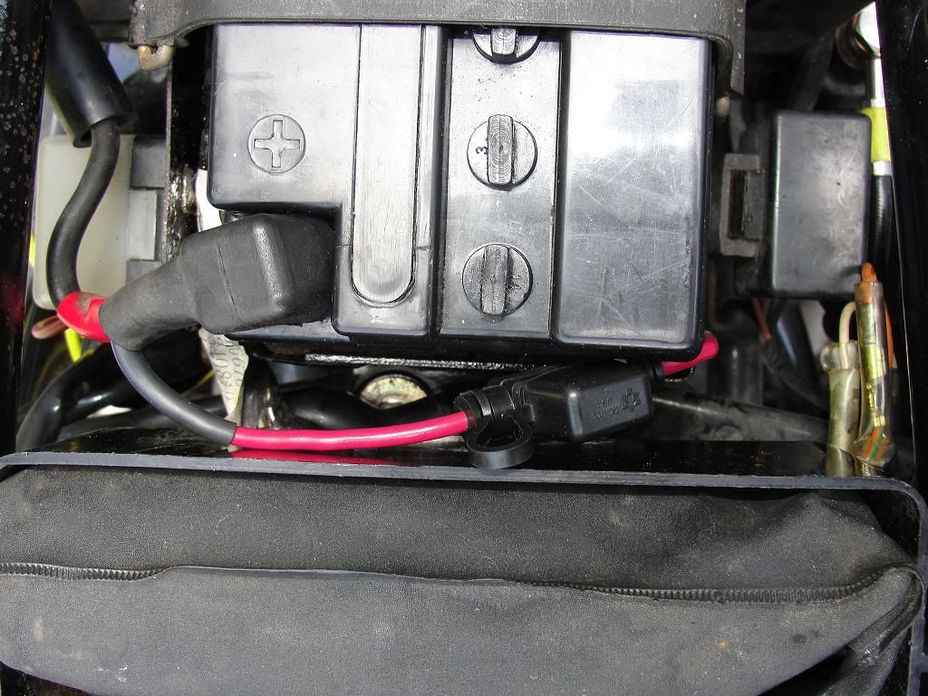
    Here is the cleaned up battery compartment, with the "Mini-Fuse" in line on the pos+ lead. I used
    a 30A fuse originally, but just changed it to a 15A as i'm thinking it's a bit safer that way. Not sure
    why roadstercycle.com uses a 30A auto reset breaker on the pos+ wire in their videos?


    On the 3 stator wire hookups, i used gold plated spade connectors that i soldered BOTH sides on,
    ....even the stator wire side. In this case they only had the female side connectors with gold plating.
    but i'm sure gold plated male connectors are available.

    Because the OEM stator wires were much thinner than the 12G i used
    on the R/R side, i folded the wires once to get a good crimp on them, and then soldered.

    Before folding the wire ends over on themselves, i lightly sanded the old wires with 220 grit
    sandpaper between my fingers. Got some copper showing
    for a good solder joint. The un-heated shrink tubing (about 5-6" on each stator wire connection),
    serves as a rain guard and is a decent friction fit over the connections. (the store didn't have the
    weatherproof type) After the pics the cover was slid back over the connection.


    ....an overall view of the install. (sheath to cover spade connection still not slid back)


    Here the protective slide cover back over the connection. I used dielectric grease to protect the connections from oxidation under the pulled over shring wrap, since the ends aren't sealed. Easy to get at the connections should the need arise.


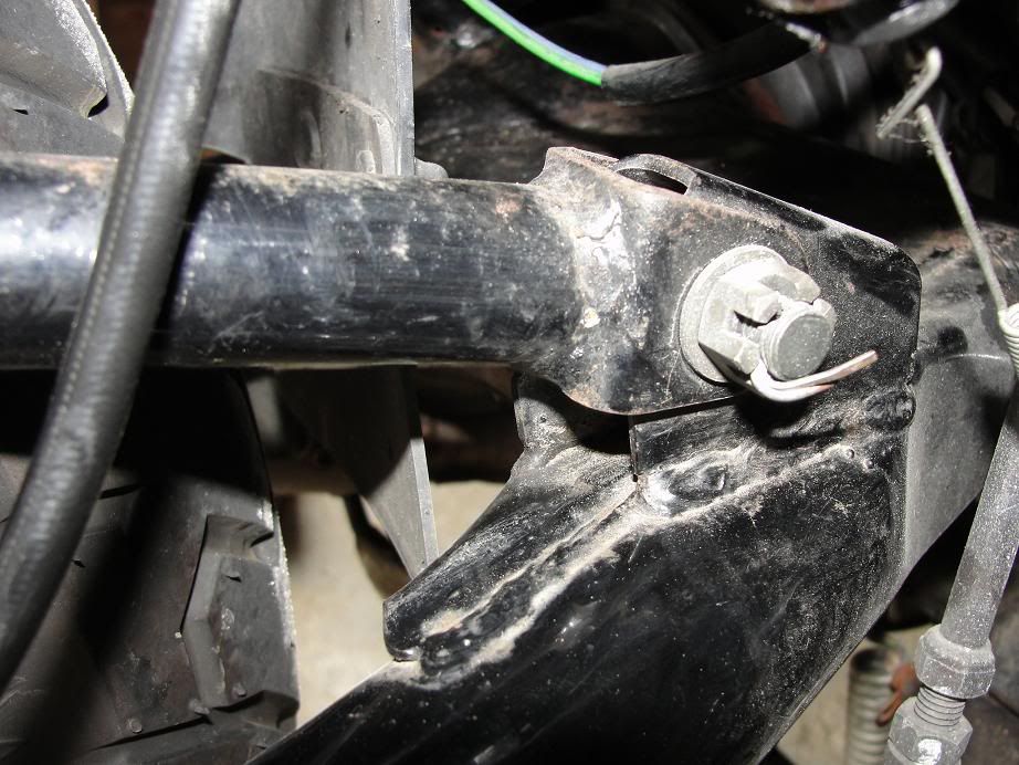
    If you have phillips screws holding your OEM R/R onto the bottom of your battery box, i guarantee
    you'll have to remove your battery box like i did to get the old R/R off!

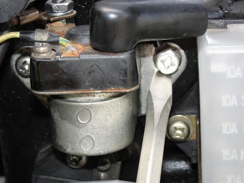
    This screw on the right side i had to hand saw a slot into, in order to get this entire side plate off.
    (so you don't have to remove the electrical parts individually)

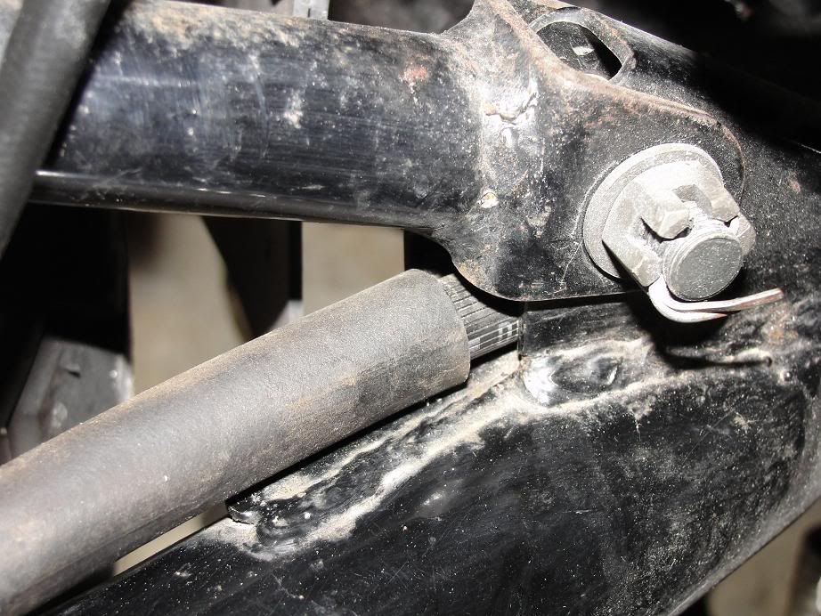
    It is the screw i'm pointing at with a large flat screwdriver blade. The new screw/bolt combination is
    one i had from an old battery connection,.....but any 6 sided bold will work fine.

    Avoid the phillips screws,....a real PITA to get off usually!

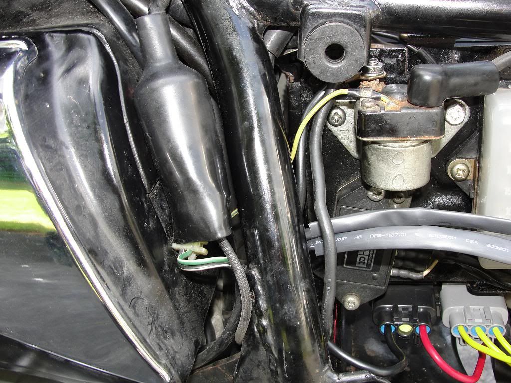
    You can see the other original phillips head on the left side of the starting solinoid,...still frozen but if
    the solinoid needs replacing i'll deal with it then.


    The 2 rectangular shaped componants under the right side cover just lift off that side of the battery box:


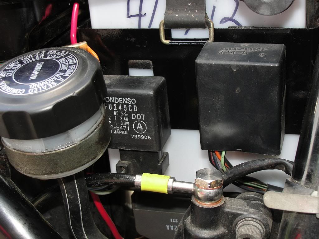
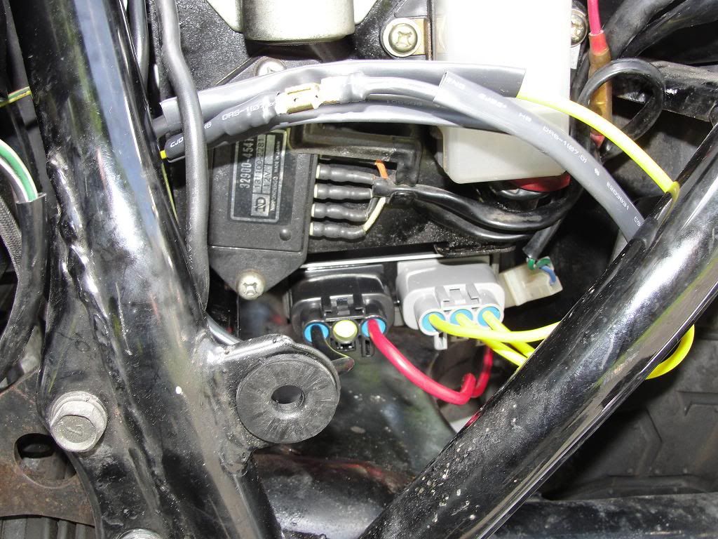
    An overall view of the unit installed:


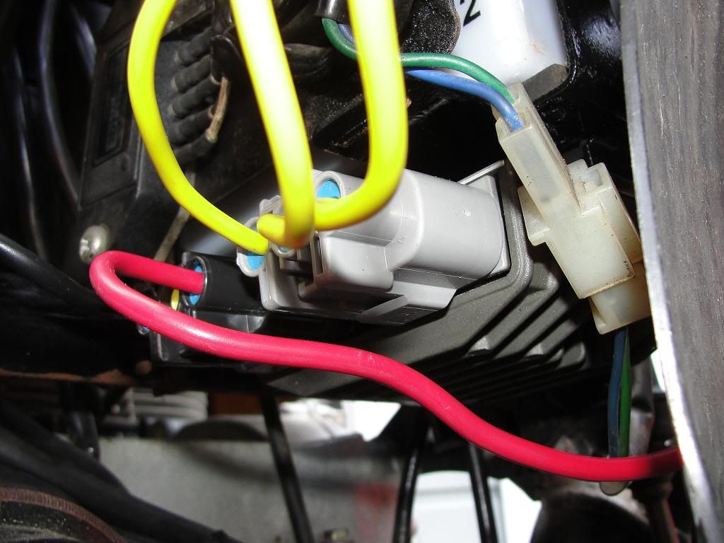
    I pulled the red wire down a bit to better show the nice plugs on this unit.....well sealed with the rubber
    plugs the wires go through.

    ......closer view,....really like the removable connections on this FH012AA R/R, and it's NOW mounted
    with 6 sided bolts to allow easy removal without having to tear out the battery box next time.


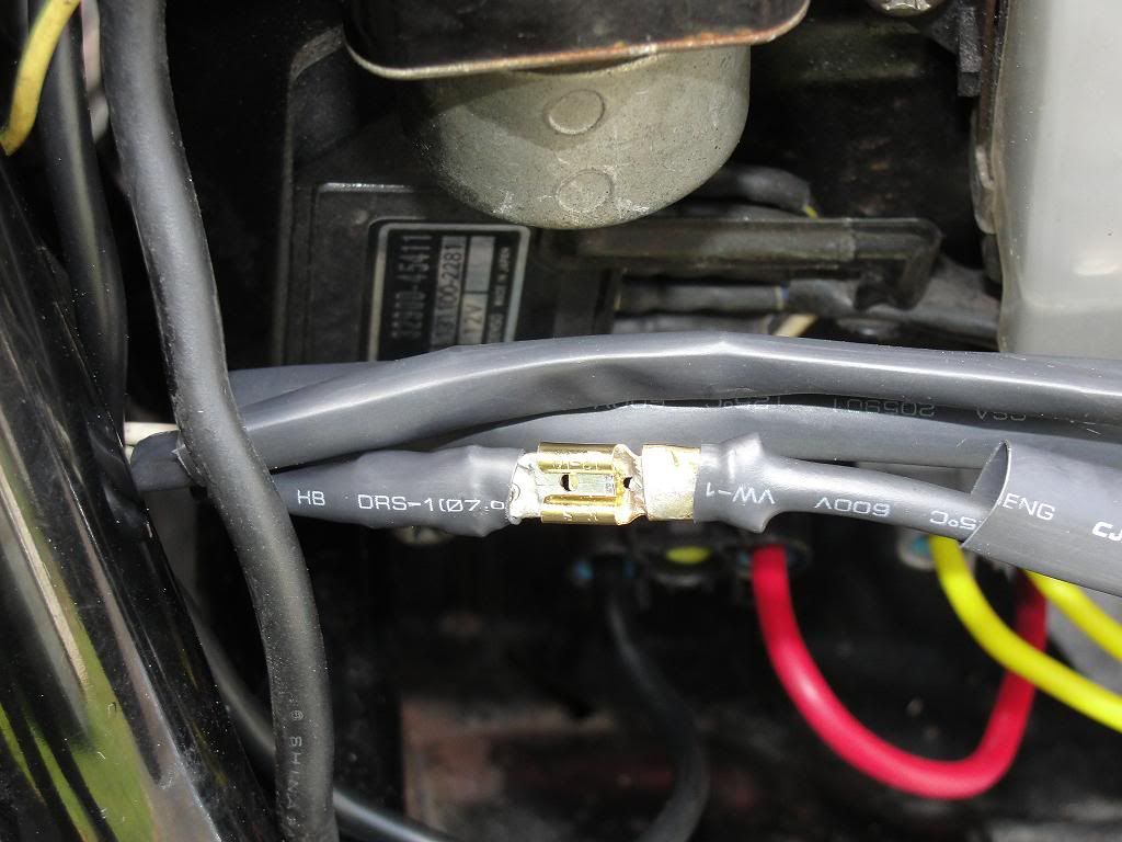
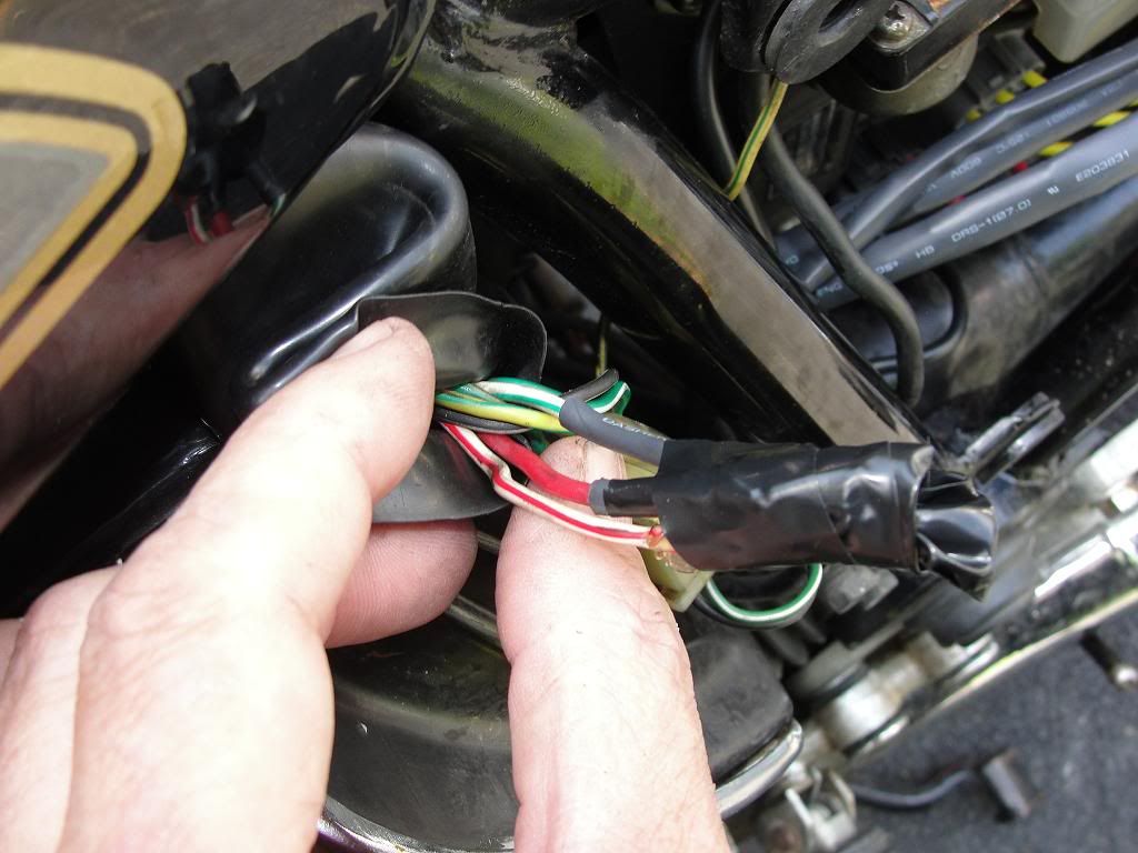
    This is where some of the original stator wires connected under the left side cover.....i used heat shrink
    tubing on the 2 male bullet connectors, .....the female connector was already protected with it's vinyl
    cover. Then used electrical tape to keep them separate. Others will know these are no longer being used.
    (especially the crap routing to the headlight area!)


    .....and here neatly covered back up with the OEM rubber wire bundle sheath:

    Last edited by Guest; 06-09-2012, 02:06 PM.

    Comment


      #17
      BTW,....thought i would show a few pics of the new HEL SS brake line hoses i installed
      a few weeks ago up front. (back line done 2 days ago also)

      I had the 3 piece set for the front made with plain SS banjos, with a black outer covering to
      match everything else. D

      I didn't want a flashy red or other color for the hoses,.......

      .......after all,.....she IS a respectable older LADY!


      Do yourself a favor and pick up a set of stainless steel "Speed Bleaders"! These have a brass inner core, but the main body is SS.
      Makes short work of getting the fluids replaced, and come with a thread sealant already installed. (no chance for air to get in along the threads!)

      .......best $13 i've ever spent for each nipple!

      Over the winter looks like a touchup to the paint on the calipers might be in order!

      I'm not sure how they might look stripped of all paint either,....but might make sense for this area!


      Here you can make out the connection of the rear HEL SS brake line at the master cylinder,....along the bottom.
      The HEL rear brake line was much shoter than the original rubber one, but made for a more sensible connection.

      The original OEM rubber hose went right past the rear master cylinder, then up and back around to connect pointing
      to the rear of the bike. Not only wasted length, but i HAD to cut the original hose in order to get it off.
      The hose went through a solid metal opening on the swing arm that the banjo had NO chance to fit through!

      .....how in the world was the average home mechanic supposed to replace the rear hose at the recommended
      2 year interval, when at least one banjo has to be fitted AFTER the hose is layed out along the original route?

      Last edited by Guest; 06-08-2012, 05:25 PM.

      Comment


        #18
        Originally posted by joejeweler View Post
        ... how in the world was the average home mechanic supposed to replace the rear hose at the recommended 2 year interval, when at least one banjo has to be fitted AFTER the hose is layed out along the original route?
        I have not replaced the hose, but I have had it fully removed from the bike with no problems.

        I presume you are referring to the loops that hold the hose to the swingarm? They are only attached on one side. Lift the other side slide the hose in, tap the retainer loops back down with a hammer.

        .
        sigpic
        mine: 2000 Honda GoldWing GL1500SE and 1980 GS850G'K' "Junior"
        hers: 1982 GS850GL - "Angel" and 1969 Suzuki T250 Scrambler
        #1 son: 1986 Yamaha Venture Royale 1300 and 1982 GS650GL "Rat Bagger"
        #2 son: 1980 GS1000G
        Family Portrait
        Siblings and Spouses
        Mom's first ride
        Want a copy of my valve adjust spreadsheet for your 2-valve per cylinder engine? Send me an e-mail request (not a PM)
        (Click on my username in the upper-left corner for e-mail info.)

        Comment


          #19
          My current bike has a Compufire as recommended by Pos/Jim, but I've installed a few of these FET type R/R's and recommend them over the other shunt alternatives. Didn't feel like paying for those fancy connectors, although they are very nice, so the wires were attached with naked spade terminals and then the cavity was filled with MIL-SPEC grade silicone sealer that doesn't attack electrics (no acid). Looks a bit getto but works well.

          Ed

          To measure is to know.

          Mikuni O-ring Kits For Sale...https://www.thegsresources.com/_foru...ts#post1703182

          Top Newbie Mistakes thread...http://www.thegsresources.com/_forum...d.php?t=171846

          Carb rebuild tutorial...https://gsarchive.bwringer.com/mtsac...d_Tutorial.pdf

          KZ750E Rebuild Thread...http://www.thegsresources.com/_forum...0-Resurrection

          Comment


            #20
            Originally posted by Nessism View Post
            My current bike has a Compufire as recommended by Pos/Jim, but I've installed a few of these FET type R/R's and recommend them over the other shunt alternatives. Didn't feel like paying for those fancy connectors, although they are very nice, so the wires were attached with naked spade terminals and then the cavity was filled with MIL-SPEC grade silicone sealer that doesn't attack electrics (no acid). Looks a bit getto but works well.


            Hehe,.....the "fancy" connectors were $22.95 on ebay,....not cheap, but then the silicone sealer can get costly too, but i'm thinking you already had some lying around.

            BTW,....surprised you used phillip head screws with the new R/R mount up???

            After all the trouble i had getting the 30 year old stock screws loose, the replacement 6 sided bolts i used will save me some aggravation should i ever need to take the R/R out. (as will the matching "pull-off" connectors! )

            Spade connectors just as effective, but i guess had the matching connectors not been available i would have turned down some water faucet washers to fit each wire hole. The 10g and 12g wires i used pretty close to filling the normally used center screw hole. Then a pop in/off fit.

            Edited to add: Oops,...just noticed you mounted it on the side, and not on the bottom of the battery box like the original. So the screws are accessable at least. Bolts or allen heads still my 1st choice on any replacements, however.
            Last edited by Guest; 06-09-2012, 12:54 PM.

            Comment


              #21
              The R/R mounting point as shown in my photo is the stock spot for the 1980 chain drive 1000. The R/R is mounted vertically so water won't sit on the terminals, so the silicone most likely isn't even needed.
              Ed

              To measure is to know.

              Mikuni O-ring Kits For Sale...https://www.thegsresources.com/_foru...ts#post1703182

              Top Newbie Mistakes thread...http://www.thegsresources.com/_forum...d.php?t=171846

              Carb rebuild tutorial...https://gsarchive.bwringer.com/mtsac...d_Tutorial.pdf

              KZ750E Rebuild Thread...http://www.thegsresources.com/_forum...0-Resurrection

              Comment


                #22
                Originally posted by Nessism View Post
                The R/R mounting point as shown in my photo is the stock spot for the 1980 chain drive 1000. The R/R is mounted vertically so water won't sit on the terminals, so the silicone most likely isn't even needed.

                I see,....much more accessable spot than on my '82 850GL. I didn't know any of the early GS's had the R/R located there. Wonder why they changed the location when it's "obvious" (as used by many of today's modern bikes) that the side is a more practicle spot.
                Last edited by Guest; 06-09-2012, 02:03 PM.

                Comment


                  #23
                  Originally posted by Steve View Post
                  I have not replaced the hose, but I have had it fully removed from the bike with no problems.

                  I presume you are referring to the loops that hold the hose to the swingarm? They are only attached on one side. Lift the other side slide the hose in, tap the retainer loops back down with a hammer.

                  .
                  Nope,...i did make use of the fold over bushing clamp/holders,.....2 on my swing arm to hold the rear brake hose in place.

                  BUT,......the hose was also fed thru the under part of the bracket that connects the bar from the rear caliper to the swingarm. (a bit dusty down there )


                  The "original" (marked 7/81) rear brake hose was like this, with NO WAY either banjo end was going through!
                  ....it'a a solid welded on bracket......so one banjo was fitted after the hose was run. (The caliper end most likely)

                  As i mentioned, the new rear brake line is shorter, and doesn't take the long route past the master cylinder and up & over only to come back to the MC for banjo hook up..

                  Last edited by Guest; 06-09-2012, 06:05 PM.

                  Comment


                    #24
                    Originally posted by Nessism View Post
                    My current bike has a Compufire as recommended by Pos/Jim, but I've installed a few of these FET type R/R's and recommend them over the other shunt alternatives. Didn't feel like paying for those fancy connectors, although they are very nice, so the wires were attached with naked spade terminals and then the cavity was filled with MIL-SPEC grade silicone sealer that doesn't attack electrics (no acid). Looks a bit getto but works well.

                    Just accomplished this upgrade. Bike running/charging better than ever. $40 total investment... with use of Mike's top-shelf crimp tool. Thanks again Ness for the hook-up.
                    '80 GS1000ST
                    '92 ZX-11
                    Past rides: '79 GS1000SN, '84 GPZ900R

                    http://totalrider.com/

                    Comment


                      #25
                      great..........

                      Comment


                        #26
                        Getting ready to do this.. but... i cant find diagram showing the which wires go where no the new R/R

                        Comment


                          #27
                          Originally posted by Nessism View Post
                          My current bike has a Compufire as recommended by Pos/Jim, but I've installed a few of these FET type R/R's and recommend them over the other shunt alternatives. Didn't feel like paying for those fancy connectors, although they are very nice, so the wires were attached with naked spade terminals and then the cavity was filled with MIL-SPEC grade silicone sealer that doesn't attack electrics (no acid). Looks a bit getto but works well.

                          What is mil-spec silicone?? I bought a mosfet RR off of ebay. HMMMM, do I want to pay another $30 for the special connectors?
                          How do I tell which of the two connectors is pos/neg??

                          Comment


                            #28
                            I like the Honda RRs, they fit exactly in the original mounting locations, have wires built in that are easy to connect to, cost very little, and never fail.

                            I sold a few hundred of them over the years to fellow GSR members, it was quite a successful campaign.
                            1981 GS650G , all the bike you need
                            1980 GS1000G Power corrupts, and absolute power corrupts absolutely

                            Comment


                              #29
                              Originally posted by gearhead13 View Post
                              What is mil-spec silicone?? I bought a mosfet RR off of ebay. HMMMM, do I want to pay another $30 for the special connectors?
                              How do I tell which of the two connectors is pos/neg??
                              I used Dow Corning 3145. Low acid so it doesn't attack electrical connectors. It's pretty expensive. I think Permatex makes some RTV they advertise as "sensor safe". If you google "electronic grade rtv" there is lots of good info.... such as this... http://www.audiokarma.org/forums/arc.../t-261645.html

                              As for which wire goes where, look at the photos already posted in this thread and everything should be obvious.
                              Ed

                              To measure is to know.

                              Mikuni O-ring Kits For Sale...https://www.thegsresources.com/_foru...ts#post1703182

                              Top Newbie Mistakes thread...http://www.thegsresources.com/_forum...d.php?t=171846

                              Carb rebuild tutorial...https://gsarchive.bwringer.com/mtsac...d_Tutorial.pdf

                              KZ750E Rebuild Thread...http://www.thegsresources.com/_forum...0-Resurrection

                              Comment

                              Working...
                              X