Announcement

Collapse
No announcement yet.

Ground frame locations

Collapse
X
 
  • Filter
  • Time
  • Show
Clear All
new posts

    Ground frame locations

    Hey guys,

    I bought a new harness for my basket case and while anywhere on the frame will work, wanted to know where exactly the original frame ground locations were.

    Looking over the wiring harness at basscliff's site, I see two right in the middle that appear to be grounded to the frame with the addition of negative battery connecting to the block.

    I also found this post:


    and anticipate adding those extra wires as well.

    #2
    Originally posted by Sphynx88 View Post
    Hey guys,

    I bought a new harness for my basket case and while anywhere on the frame will work, wanted to know where exactly the original frame ground locations were.

    Looking over the wiring harness at basscliff's site, I see two right in the middle that appear to be grounded to the frame with the addition of negative battery connecting to the block.

    I also found this post:


    and anticipate adding those extra wires as well.
    It varies model to model, but many are as shown
    one to the starter solenoid
    one to the frame (usually at the front of the battery box)


    go look at your manual for the info.


    Just bear in mind, in applying this to your bike, you are trying to achieve a single point ground (any where) that collects all ground currents and delivers them to the R/R(-) on the shortest wire practical. Ground currents come from
    1. Frame
    2. Harness (B/W)
    3. Battery(-)


    Last edited by posplayr; 04-16-2014, 05:02 PM.

    Comment


      #3
      POS I'm going to ask what is possibly a stupid question after reading through all your grounding threads..

      I had recently bought a master grounding block (the one from EC). My original intention was to connect all my ground points (Harness, r/r) to this and then connect this to the negative terminal of the battery. Clearly given you Analysis this is the incorrect approach.

      However if i run the RR , The frame grounds and your added battery Negative to tho the master grounding block and them ground the Block at the frame am i achieving the same result

      Comment


        #4
        Originally posted by GS(X)400 View Post
        POS I'm going to ask what is possibly a stupid question after reading through all your grounding threads..

        I had recently bought a master grounding block (the one from EC). My original intention was to connect all my ground points (Harness, r/r) to this and then connect this to the negative terminal of the battery. Clearly given you Analysis this is the incorrect approach.

        However if i run the RR , The frame grounds and your added battery Negative to tho the master grounding block and them ground the Block at the frame am i achieving the same result
        Not sure what you are asking. The SPG should be mounted within no more than 1 ft of the r/r(-). ThAt means 4 wires at the SPG. Not sure if your plan is to use a ground block for the SPG or not or even why.

        Comment


          #5
          Originally posted by posplayr View Post
          Not sure what you are asking. The SPG should be mounted within no more than 1 ft of the r/r(-). ThAt means 4 wires at the SPG. Not sure if your plan is to use a ground block for the SPG or not or even why.
          My plan originally was to use the ground block to keep all my grounds in 1 places for easy troubleshooting and neatness. So I guess i was trying to make a SPG. The ground block has way less than a foot of wire between the RR currently

          Is there a reason I cant or should not use the master ground block as my SPG ? It would seem by connecting the block to the battery NEG I am adding that extra run of wire from the batter to the SPG as you have suggested in the diagram.
          Last edited by Guest; 09-12-2014, 11:20 AM.

          Comment


            #6
            I don't realy understand the question because I don't really know what you are asking. You have described a ground block from CE. Sorry I don't know which one that is. Then you say you are going to connect it to the negative side of the battery; does that mean physically mount it to the battery or run a wire?

            if you replicate all of the paths shown in the figure you will active the original intent. If you move the SPG to a battery post you have clearly changed it.

            Comment


              #7
              I see I need to redraw the picture. I have one sketched up but need to do some other things today. perhaps over the weekend. This will be nothing new, just make it more understandable by focusing primarily on all the voltage drops between the battery and R/R.

              Comment


                #8


                This is the unit i have installed as my SPG. I have the main wire from the back running to the NEG terminal battery Terminal with 1 of the Harness grounds and the RR Ground running directly to the same PIN. From your diagram the only run I need to add is the Wire from the Frame ground to the SPG.

                I will perhaps wait for your next diagram to see if it clears things up for me.
                Attached Files

                Comment


                  #9
                  Originally posted by GS(X)400 View Post


                  This is the unit i have installed as my SPG. I have the main wire from the back running to the NEG terminal battery Terminal with 1 of the Harness grounds and the RR Ground running directly to the same PIN. From your diagram the only run I need to add is the Wire from the Frame ground to the SPG.

                  I will perhaps wait for your next diagram to see if it clears things up for me.

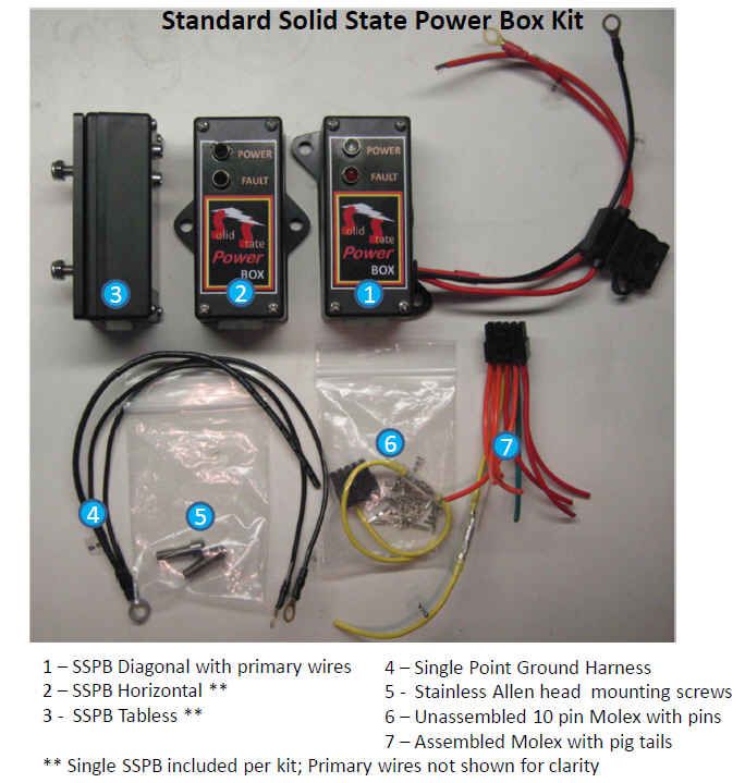
                  Yes that works, but in fact (I think) the cleanest approach and one that has the least sensitivity to corrosion is the SPG Harness #4 in the picture below. This is what I provided with the SSPB.

                  For a Single Point Ground ring lung, I basically just crimp and solder 3 wires together (10 ga ring lug).

                  • 14ga R/R(-) sripped wire to be soldered to the R/R(-) wire return.
                  • 16ga Battery(-) with crimped and soldered ring lug at the other end
                  • 16ga Frame - with crimped and soldered ring lug at the other end


                  You can then just stack the SPG ring lug with the B/W Harness ring lug (use contact cleaner or dielectric grease) and mount it anywhere. With this setup the only place where corrosion can reduce the voltage at the battery post connection.
                  The B/W harness ground could have been crimped in as well, if it was made on the spot, but that contact surface does not have ant effect on charging voltage so it is more convenient to leave it out.

                  You just mount the SPG ring lug to a convenient mounting molt on the side plate or frame and you are done.generally I pick the side plate as it needs grounding in order to provide the current return for the solenoid. The G models are a little different to the E models in this regard so there might be some variations.

                  This really is putting a fine point on the solution. It is finding the best configuration that will age/corridor while creating the least impact to charging.

                  With the ground post, what happens when it corrodes? How many contact surfaces are there that have to conduct current that are in the battery R/R circuit?


                  Last edited by posplayr; 09-12-2014, 05:20 PM.

                  Comment

                  Working...
                  X