.png "Powered by vBulletin")
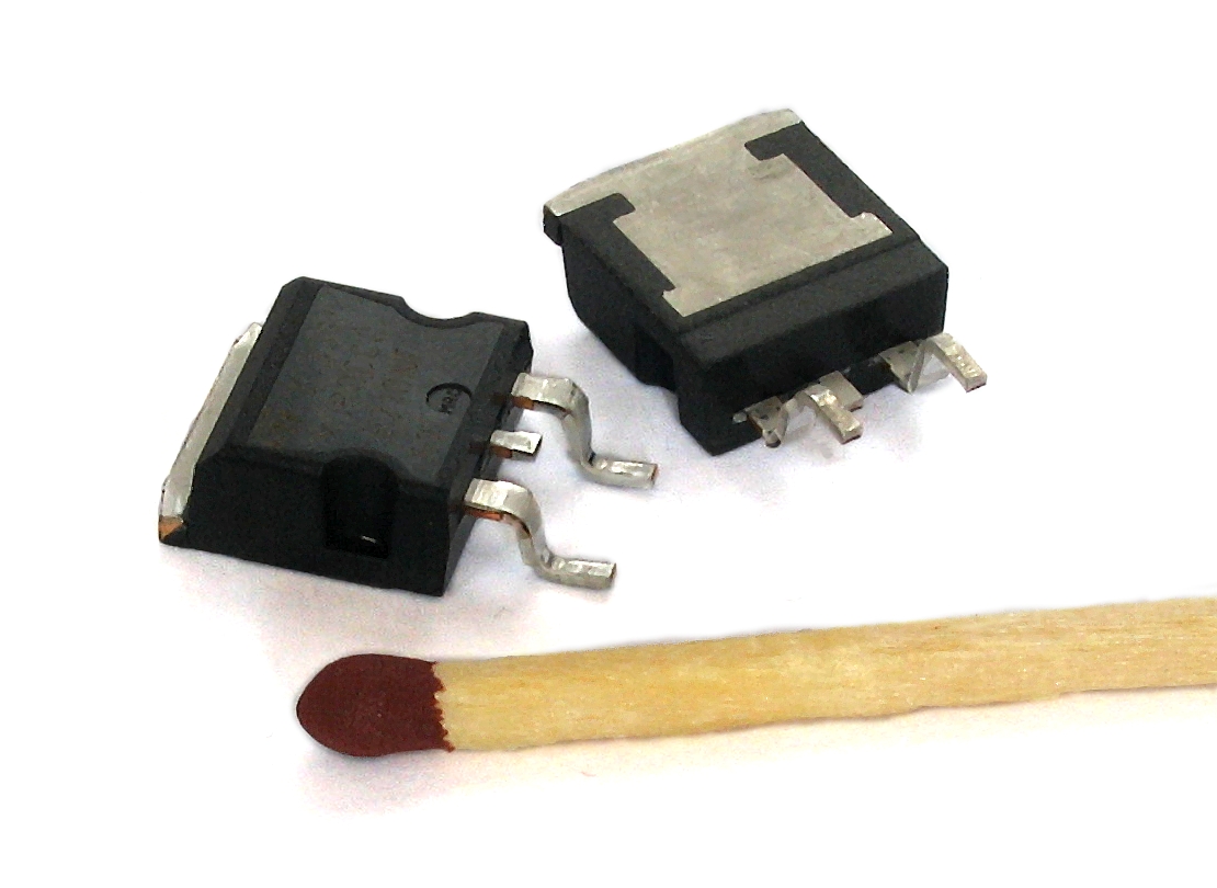
FH012 Benefits
While we EE's could debate the relative merits of different regulator approaches till the cows come home, I will try and summarize why this FET technology really represents a break through for the average GS owner.
The topology of the FET approach is significantly different from the other R/R configurations in that it combines two of the primary functions of the classic shunt R/R into a more sophisticated function which switches FET's on and off to achieve the same function. Because of this direct control of the power waveforms, higher efficiency and regulation can be achieved.
The inexpensive power generation approach used on many of these early motorcycles used a simple permanent magnet generator. The faster the motor spins the more power is generated. There is no way to control the magnetic Field in the generator as is done on a more sophisticated generator or alternator. Feild control limits the output power; without it you have to dump generator power somewhere.
So the problem that falls to the R/R is to convert all of this energy into DC and get rid of the excess that the battery and charging system can't use. The approach is rather brute force. The stator output legs are "crow bar"ed. That is essentially directly shorting the power leads coming from the stator. Ouch; as you can imagine things get hot, both the R/R and the stator.
So to summarize why the FET approach is potentially better I'll elaborate on some practical points for the layman below.
1.) The FET approach doesn't implement a classic full wave diode bridge rectifier. So if the old regulators are producing 10 amps of current, then there is about 2x2Vx10amps=40 watts being dissipated in the old R/R alone because there are always two diode legs in saturation (e.g. 2V drop).
The FET style drops this in 1/2 because the lower leg of the effective diode bridge is implemented with FET's which essentially have no forward drop in comparison. Both side could have been implemented in the FH012 but they chose to only do one side.
2.) Because the FET regulator is not dropping a full +4 volts across the discrete diode bridge, there is more voltage available to the output and a higher output voltage at minimum RPM can be achieved (say 14.25V v.s. 12.8V for the OEM R/R).
3.) Because the regulation is implemented using FET switches as well, the sensing function is separated from the electrical control and so more precise regulation can occur (no over charging to above 14.5 V like the stock GS which can go to 15.5V as per the manual). The FH012 is specified to 14.5 +/- .3 v max. This is much better than the OEM.
4.) NIX THIS ADVANTAGE IT DOESNT EXIST:
This last element is a bit of conjecture, but in principle at least, the FET based control doesn't have to shunt current to control the maximum output voltage. It is possible to simply disconnect the stator windings from the R/R output. This should dramatically improve the life of the stator windings !!Whereas the OEM R/R shunts, shorting the stator winding producing very high currents in the stator, creating thermal stress and eventually smoking the windings.
In contrast, the FET approach could simply let the stator go open circuit and no current flows.
I'm going to test and see if I can find any evidence this is how the FH012 is implemented.
The FET approach still appears to shunt, it just does it more precisely.
I know it regulates very well
.
Pos
While we EE's could debate the relative merits of different regulator approaches till the cows come home, I will try and summarize why this FET technology really represents a break through for the average GS owner.
The topology of the FET approach is significantly different from the other R/R configurations in that it combines two of the primary functions of the classic shunt R/R into a more sophisticated function which switches FET's on and off to achieve the same function. Because of this direct control of the power waveforms, higher efficiency and regulation can be achieved.
The inexpensive power generation approach used on many of these early motorcycles used a simple permanent magnet generator. The faster the motor spins the more power is generated. There is no way to control the magnetic Field in the generator as is done on a more sophisticated generator or alternator. Feild control limits the output power; without it you have to dump generator power somewhere.
So the problem that falls to the R/R is to convert all of this energy into DC and get rid of the excess that the battery and charging system can't use. The approach is rather brute force. The stator output legs are "crow bar"ed. That is essentially directly shorting the power leads coming from the stator.
Ouch; as you can imagine things get hot, both the R/R and the stator.So to summarize why the FET approach is potentially better I'll elaborate on some practical points for the layman below.
[Point #1 and #2 was validated by showing a reduced dropout voltage, increased output voltage]
The FET style drops this in 1/2 because the lower leg of the effective diode bridge is implemented with FET's which essentially have no forward drop in comparison. Both side could have been implemented in the FH012 but they chose to only do one side.
2.) Because the FET regulator is not dropping a full +4 volts across the discrete diode bridge, there is more voltage available to the output and a higher output voltage at minimum RPM can be achieved (say 14.25V v.s. 12.8V for the OEM R/R).
Point #3 is true, but it also appears true for both the Honda unit as well as a CBR linear regulator. The OEM unit appears unique here in that it does crappy closed look regulation
4.) NIX THIS ADVANTAGE IT DOESNT EXIST:
This last element is a bit of conjecture, but in principle at least, the FET based control doesn't have to shunt current to control the maximum output voltage. It is possible to simply disconnect the stator windings from the R/R output. This should dramatically improve the life of the stator windings !!Whereas the OEM R/R shunts, shorting the stator winding producing very high currents in the stator, creating thermal stress and eventually smoking the windings.
In contrast, the FET approach could simply let the stator go open circuit and no current flows.
I'm going to test and see if I can find any evidence this is how the FH012 is implemented.
The FET approach still appears to shunt, it just does it more precisely.
I know it regulates very well
(as does the Honda)
Pos


.png)

 What can I say? "watta u want a boiled battery or a fried stator?
Comment