.png "Powered by vBulletin")
Coming along very nicely. Good work.
-
-
I'm looking into adding relays...found some at all electonics, but they're 40 amp....too high?Comment
-
Bob,Originally posted by 80GS850GBob View Post
For the sake of using something that is widely available at most auto parts stores, I suggest using whats called an "ice cube" relay - that's a generic term. These relays are manufactured by bosch/tyco/hella/panasonic and are approximately a 1" cube with a small mounting bracket integrated into them. The normally-open side is typically rated at 40A and the normally closed side is rated at 30A.
http://www.cycleterminal.com/accessory-relays.html (see the mini-relay section)
Your main concerns in selecting a relay are:
1. It's load-side current capacity
2. It's physical size (where are you trying to put it?)
Nothing on our bikes draws more than 40A (except for the starter, which you wouldn't be using a relay for, anyway).
Hope this helps.Cogito ergo sum - "I think, therefore I am"
René DescartesComment
-
The rating is way over kill, but at a duty rating of 40a and an actual use of up to 15a they should last nearly forever...well, at least for a very long time sans any major shorts in the affected circuits.Originally posted by philosopheriam View Post
A small/compact size only adds to the usefulness do to adding things in that were never there to begin with....I'd figure adding relays for the following;
-horn
-high beam
-low beam
...maybe the turn signal circuit too
I want to go one size bigger in the wiring, like you did, in order to cut down voltage drops{thin gauge wire/corrosion @ connectors} , add more grounds and use better{new} connectors too.....in other words set her up for a trouble free running. Too bad somebody like painless wiring doesn't make cycle rewire sets, but it's a cycle - there isn't much there to redo.Comment
-
Horn: definitely add a relay - these suckers can draw a lot. Granted, they are not a continuous load, i.e., you aren't sitting there for 10min with the horn energized.Originally posted by 80GS850GBob View Post
Headlamp: Ideally, using a traditional halogen headlight, you would have a circuit that powers the headlight without running that load through the dimmer switch. In essence, you might need two relays - wire the low beam to the normally closed side of relay1 and the high beam to the normally open side of relay1 and have the dimmer switch energize that relay when the dimmer switch is on HIGH. The second relay would be used for a cranking cut-out, i.e. power to relay1 goes through the normally closed side of relay2, and relay2 is energized when the start circuit is engaged, essentially cutting power to relay1 and thus the headlight will be OFF when the bike is cranking, yet once the starter is disengaged the headlight will revert to the low beam (unless the dimmer switch is in the high position). Just an idea. Halogen headlamps are excellent at cooking motorcycle dimmer switches.
I didn't use any relays for my headlight because I am using an LED sealed beam - draws 2.8A on high.Cogito ergo sum - "I think, therefore I am"
René DescartesComment
-
I thought, possible issue here, that the oem starter relay would effectively kill power to everything except the starter...am I wrong?Originally posted by philosopheriam View Post
You went with an LED headlight...which one? I was thinking about the newer Cree HD versions since they have less dead zone in front of the cycle when lit...saw a few versions out there with u tube vids that show said dead zone...kind of scary.Comment
-
The oem starter relay doesn't kill power to anything at all. That's why some (including myself) have added a relay to cut power to the headlight during startup, thus leaving as much power as possible for cranking the starter.Originally posted by 80GS850GBob View Post
1983 GS750ED-Horsetraded for the Ironhead
1981 HD XLH
Drew's 850 L Restoration
Drew's 83 750E ProjectComment
-
Well, now I feel stupid...I assumed that cycles were like cars in that aspect. I guess I never paid attention all the years I hit the starter button - guess I should have.Originally posted by jsandidge View Post
Ok, sign me up for a relay for that!Comment
-
Folks,
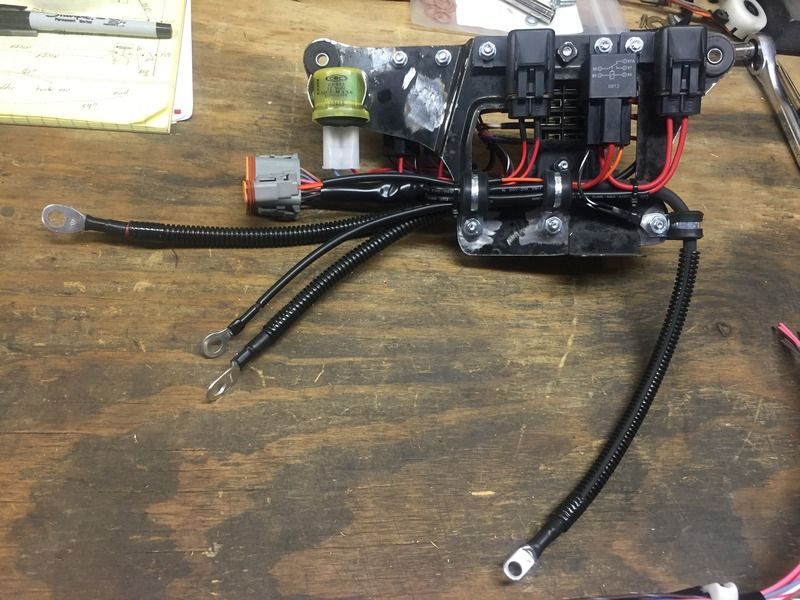
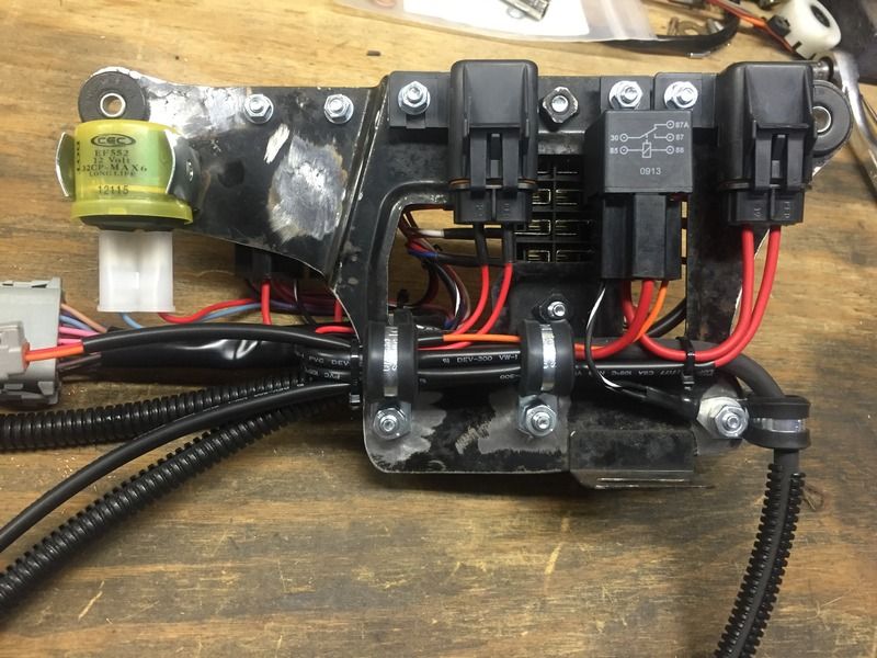
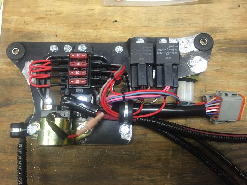
Thanks for all of the kind words and compliments - I once again apologize for not posting updates in a more timely fashion. Over the past couple weeks, life has been getting in the way of finishing the wiring. Unfortunately, the biggest obstacle to progress is me - a wise man once said "don;t let perfection be the enemy of good." Well, when you're borderline OCD and wan't everything to be near-perfect, things can take a bit longer than expected. Here are some photos of the finished fuse panel, iteration #3.
I was having difficulty getting the wires to lay how I envisioned them - everything has to "flow" and look like a plan. Moreover, the vibration on a motorcycle can cause wires to chafe, so, wire positioning and the addition of sheathing is important. The plate holder itself will be powdercoated when ALL of the electrics are finished.
Cogito ergo sum - "I think, therefore I am"
René DescartesComment
-
Nice. As an hvac service tech ocassionally dealing with control wiring, I appreciate nicely laid out wiring. It makes me crazy when I go to a site and the wiring is like spaghetti.sigpic
When consulting the magic 8 ball for advice, one must first ask it "will your answers be accurate?"
Glen
-85 1150 es - Plus size supermodel.
-Rusty old scooter.
Other things I like to photograph.....instagram.com/gs_junkie
https://www.instagram.com/glen_brenner/
https://www.flickr.com/photos/152267...7713345317771/Comment
-
Properly loomed is the only correct way! Anything else is incorrect.
Kills me when I see underwood shots of a nice engine and there is spaghetti wires everywhere.
Very nice job on the wiring, glad I am not the only OCD person in this world 1978 Gs1085 compliments of Popy Yosh, Bandit 1200 wheels and front end, VM33 Smoothbores, Yosh exhaust, braced frame, ported polished head
1983 Gs1100ESD, rebuild finished! Body paintwork happening winter 2017
I would rather trust my bike to a technician that reads the service manual than some backyardigan that THINKS HE KNOWS how to fix things.Comment
-
Considering the number of mechanical relays you are using it looks very clean and well laid out. It took me a moment to see you are doing and inside and outside mount of the side plate. Are you using a smaller battery as well to make up room on the inside?
There are some pretty heavy wires there, but I'm guessing two are for the primary (+) battery feed to the starter. Not clear about the other two, one larger than the other.
Where is the R/R going?Comment
-
The three relays are for the following: Horn (front side), Ignition/coils (front side), Main (rear side)Originally posted by posplayr View Post
The two waterproof fuse holders are for the following: Keyswitch, Main
There are two 8ga cables in the photos - one is for battery positive to the starter solenoid (there will be another cable from the NO side of the solenoid to the starter once the panel is installed). The other 8ga cable is battery negative that runs to the block of the engine. Next to the 8ga battery negative there is a 12ga wire with a ring terminal, this wire grounds the fuse panel and all of the relays/solenoids. When the panel is installed, a short 12ga wire will connect the fuse panel to the motorcycle frame.
Although I reoriented the battery - it now sits on its end, it clears all of the relays/fuses on the backside of the fuse panel. I designed it that way :-)
The R/R is bolted to a plate behind the battery which also holds the dyna 2000 ignition. Photos will follow.Cogito ergo sum - "I think, therefore I am"
René DescartesComment
-
I also appreciate a clean wiring job. It really looks great!👍My Motorcycles:
22 Kawasaki Z900 RS (Candy Tone Blue)
22 BMW K1600GT (Probably been to a town near you)
82 1100e Drag Bike (needs race engine)
81 1100e Street Bike (with race engine)
79 1000e (all original)
82 850g (all original)
80 KZ 650F (needs restored)Comment
-
FINALLY! (Ode to Joy plays in the background)
Installed 99% of the remaining connectors, lengthened the wiring on the L handlebar multi-function switch, built some "test" turn signals from spare light bulbs, plugged everything in and tested the harness. SUCCESS!!! Everything worked flawlessly!!! A few notes before you watch the video:
1. The fuel gauge in the instrument cluster - I put a jumper in my harness connector which essentially shorts the gauge return wire to ground. The meter then goes to FULL. The circuit works as designed!
2. The pink wires which go to the ignition coils which are energized by the killswitch/ignition relay - you will see me hit the switch in the video and the relay clicks, there is voltage present and the circuit works as designed!
3. The NEUTRAL and OIL PRESSURE lights in the instrument cluster - I am manually shorting the return wires to ground via a set of jumper wires, essentially mimicking the neutral and oil pressure switches.
4. I lowered the quality of the video/audio to reduce the file size.
Cogito ergo sum - "I think, therefore I am"
René DescartesComment


Comment