Announcement

Collapse
No announcement yet.

1981 gs750 (gs750e) Retro Racer project

Collapse
X
 
  • Filter
  • Time
  • Show
Clear All
new posts

    Did the front wheel and brake discs in black


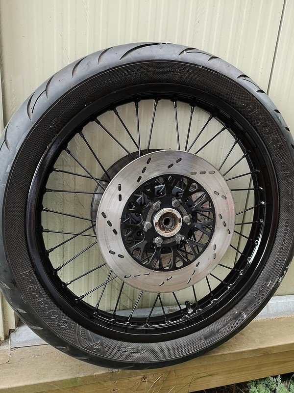
    Front wherl by Lars Krogh-Stea, on Flickr


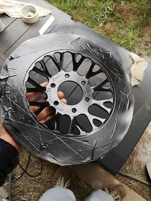
    Disc by Lars Krogh-Stea, on Flickr


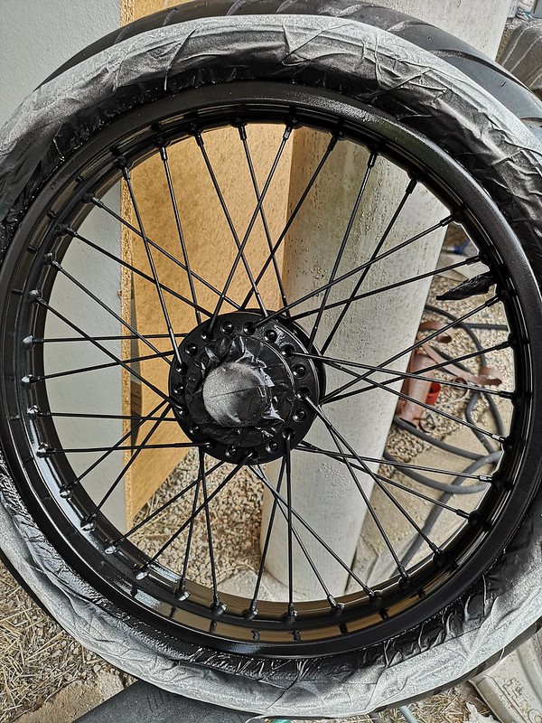
    Rim painted by Lars Krogh-Stea, on Flickr

    Comment


      The complete fork. I'll remove some of the screws for sandblasting and powdercoating later..


      Fork 2 by Lars Krogh-Stea, on Flickr

      Comment


        Borrowed the cnc-router again. This time for the top triple. Did some prototyping in oak for speed.


        L by Lars Krogh-Stea, on Flickr


        L by Lars Krogh-Stea, on Flickr


        Ordered gear indicator and warning lights from ebay. The gear indicator was awesome, but the warning lights was a big disapointment 
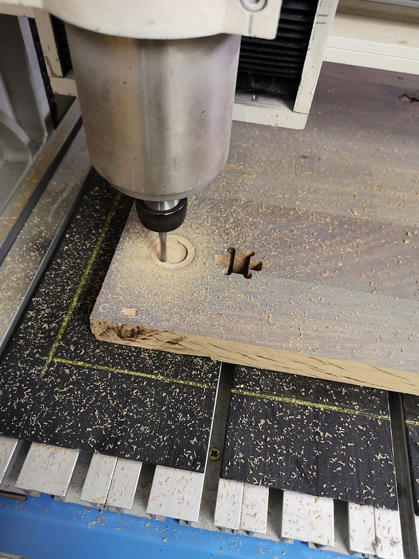
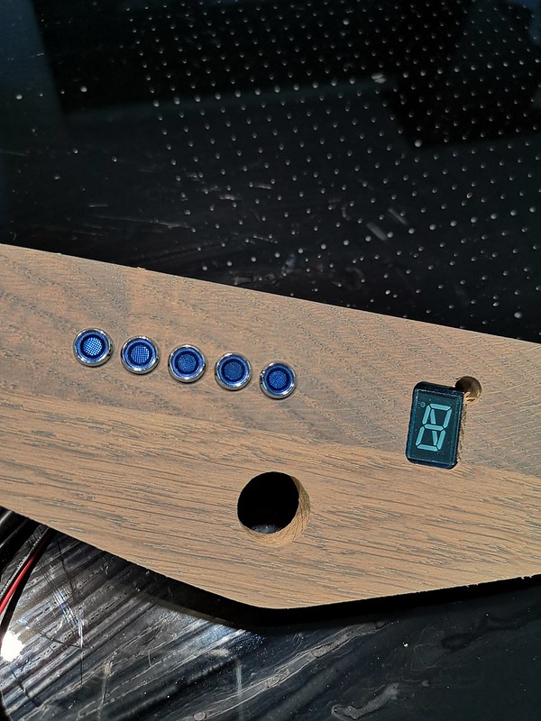
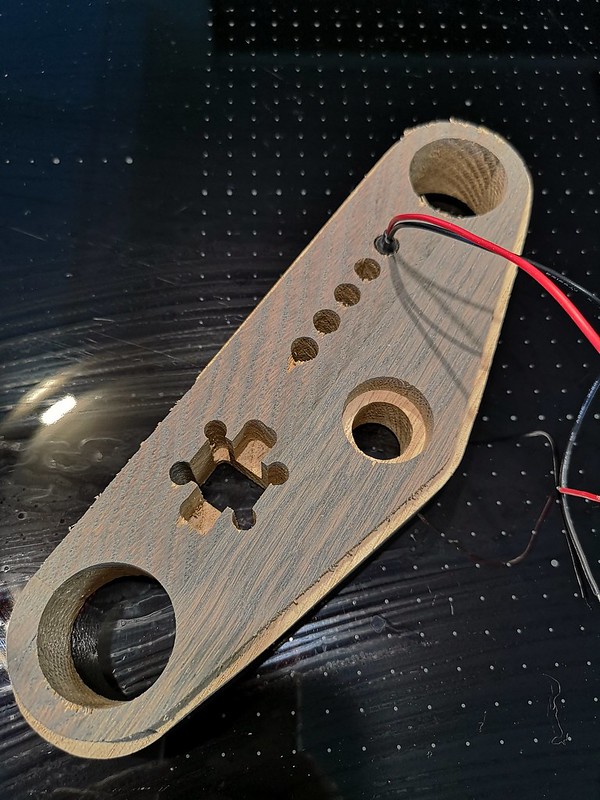
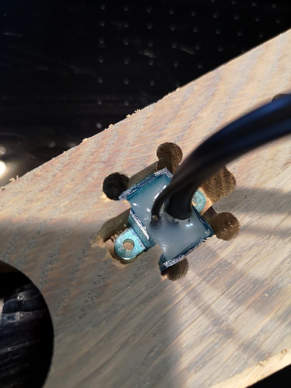
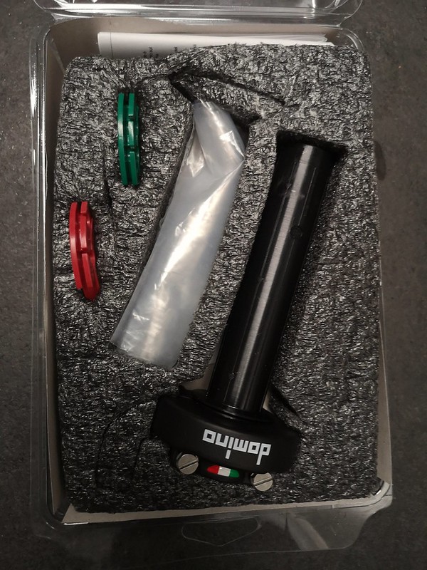
For some reason they were all blue. Waiting for another shipment with the usual blue, green, red and orange. I will also cut down to four lights and have one common light for the indicators. The reason for the hole next to the gear-indicator is that I forgot to alter the settings before testing on the oak. The aluminum I've bought is 8mm thicker and i trilled 6mm down into my friends router table


        L by Lars Krogh-Stea, on Flickr


        L by Lars Krogh-Stea, on Flickr


        The reason for the uneven outer edges is that I went too fast and broke the end mill piece. Had to use a band saw to finish it off. It's only for testing so it doesn't really matter, and I have more end mills at home.


        L by Lars Krogh-Stea, on Flickr


        L by Lars Krogh-Stea, on Flickr
        Last edited by LarsKroghStea; 09-08-2018, 04:26 PM.

        Comment


          After nearly a month of waiting... Tada..the m-unit blue ��

          Munit by Lars Krogh-Stea, on Flickr
          Last edited by LarsKroghStea; 09-08-2018, 04:25 PM.

          Comment


            I was struggling to find a good placement for the speed sensor. I've seen some people mount them in the rear brake, or under the front fender, but I will try to modify the original speedo-gear unit. That way I won't have to machine a spacer to replace it. I will drill a hole inside the original hole to place the pickup perpendicular to the magnet. Then I'll grind off some off the original gear so the magnet will sit flush.

            Sensor4 by Lars Krogh-Stea, on Flickr

            Comment


              I thought I was going deep in my build, but what you're doing with this bike is so cool.
              sigpic

              Check out my rebuild thread here: https://www.thegsresources.com/_foru...GS-750-Rebuild

              Comment


                Thanks, Sam

                I sodablasted the carburettors and dusted them of afterwards with compressed air. I thought I was careful not to get any soda inside them, but my father said I should open and clean them anyway.

                2018-09-08_08-12-08 by Lars Krogh-Stea, on Flickr

                Glad I did, because he was right. Also, although I've adjusted the needles in my zx7r and knew there were diafragms in there, I didn't know the big oval channel in the inlet was directly connected. I imagine if you blow hard enough directly in there, you might rupture the diafragms. Mine where fine, but I will clean my carburettors some other way the next time.

                Soda by Lars Krogh-Stea, on Flickr

                Comment


                  Sometimes the build finds its own path and I have to tag along to see where the build goes. I've been good at spending time on planning to minimise the need for doovers. But when I thought I found a similar exhaust on the internet as I had stowed away 3 years ago, I was dead wrong. Measurements was wrong and after countless tries to make the new exhaust look good on the bike, I gave up. I then decided to make my own. The goal was to have the same amount of stainless perforated tube as in the Kercher.

                  Exh 5 by Lars Krogh-Stea, on Flickr

                  Lucky me had some stainless perforated tube laying around.

                  Exh 4 by Lars Krogh-Stea, on Flickr

                  Took some half inch aluminum to the lathe and made the end piece. It is stepped with the same thickness as in the perforated tubing. Did also put in some set screws to secure it.

                  Exh 1 by Lars Krogh-Stea, on Flickr

                  Packed it:

                  Exh 2 by Lars Krogh-Stea, on Flickr

                  And hammered it gently in. All that is missing is a screw on the backside to keep it from moving. But I did stamp in my initials just for fun.

                  Exh 3 by Lars Krogh-Stea, on Flickr
                  Last edited by LarsKroghStea; 09-11-2018, 01:52 AM.

                  Comment


                    New throttle control with teflon lining and adjustable sensitivity


                    Throttle by Lars Krogh-Stea, on Flickr

                    Comment


                      Thanx


                      I've had a go at designing the wiring for the bike. I would be very grateful if someone would look it over and correct mistakes I'm not sure if I should connect the regulator to battery or switced plus, so it would be helpful with a hint about that too.


                      Noisemaker_koblingsskjema by Lars Krogh-Stea, on Flickr

                      Comment


                        Hi Lars,

                        The original wiring has a 15 amp fuse between the regulator and the battery.
                        It's a separate fuse as the other circuits have their own fuse.
                        It's mandatory as you could have a short say from a headlamp that would kill you regulator immediately.
                        Have you considered using the M-Lock from Motogadget?
                        I installed one yesterday and it works great.
                        BTW I believe you should also consider the diagram from a wiring harness perspective.
                        One for the rear of the bike, one for the front , one for the dashboard etc...
                        Great job!
                        sigpicJohn Kat
                        My bikes: CB 77, GS 1000 ST Cafe Racer with GSXR 1052 engine, GS 1000 ST, XR 41 Replica with GS 1085 engine,
                        GS 1100 SZ Katana with GS 1135 EFF engine, KTM Superduke 1290 R 2020

                        Comment


                          Hi John

                          I've made a new diagram with the 15 amp fuse for the charging circuit and some other modifications. All ground is now leading back to the battery via wires, the oil pressure wiring is corrected and the alternator has three wires. The m-lock is really cool and i have an rfid-circuit laying that a was planning to use. Since I have the M-unit blue I'll use the bluetooth for keyless. I'll check out your builds later

                          Noisemaker_koblingsskjema by Lars Krogh-Stea, on Flickr

                          Comment


                            I like it so far! I think it's cool you're using your router table to prototype some of the parts. I have a Shapeoko 3 and use it from time to time on stuff like this. Let me know how that aluminum piece looks after some time in the exhaust. I've been told not to mix stainless parts with aluminum parts unless one or the other has been coated (paint or some other insulator). Galvanic corrosion occurs when the two are in direct contact. I've never seen the affect of it personally but I'm curious to see what happens after a while. Let us know if there are any signs of corrosion or if it's not a big deal!

                            Comment


                              Originally posted by T8erbug View Post
                              I like it so far! I think it's cool you're using your router table to prototype some of the parts. I have a Shapeoko 3 and use it from time to time on stuff like this. Let me know how that aluminum piece looks after some time in the exhaust. I've been told not to mix stainless parts with aluminum parts unless one or the other has been coated (paint or some other insulator). Galvanic corrosion occurs when the two are in direct contact. I've never seen the affect of it personally but I'm curious to see what happens after a while. Let us know if there are any signs of corrosion or if it's not a big deal!

                              Thanks I didn't think about the reactivity between metals, but it makes sense. There's not much left of the driving season here, som I'm lucky if I get to test it this year.. But I will keep an eye on it and post pictures if anything interesting happens.

                              Comment


                                I posted the wiring diagram in the electrical section and got some pointers and ideas. This is the final rendition of the diagram. The wires are not to scale, either by length or thickness, but the diagram shows how things will be connected to eachother. The turn light switch is a returning two way switch, the others are push buttons.

                                Noisemaker_koblingsskjema by Lars Krogh-Stea, on Flickr

                                Comment

                                Working...
                                X