Announcement

Collapse
No announcement yet.

Cam Fitting Trouble -- Which Position

Collapse
X
 
  • Filter
  • Time
  • Show
Clear All
new posts

    #16
    Pictures as Promised

    These are the pics after both intake & exhaust cams have been installed and tensioner fitted and adjusted appropriately.

    Motor turned over a couple of times and then moved to TDC on 1-4 cylinders.
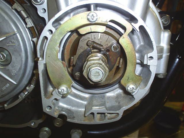


    Motor at TDC #1-4


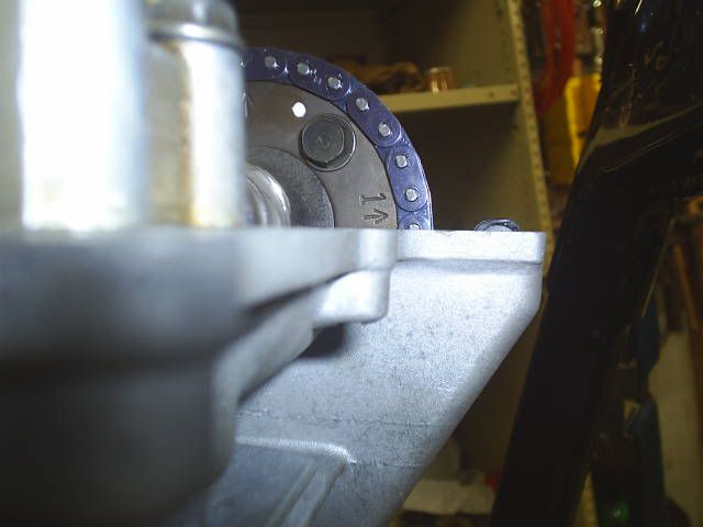
    Exhaust cam #1 arrow position when motor at TDC.


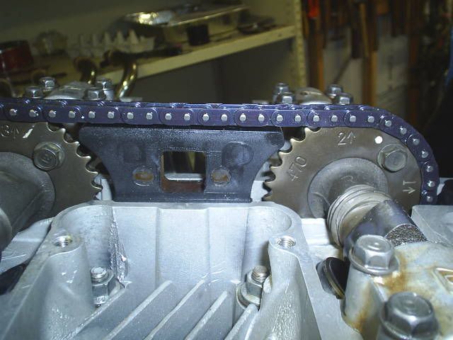
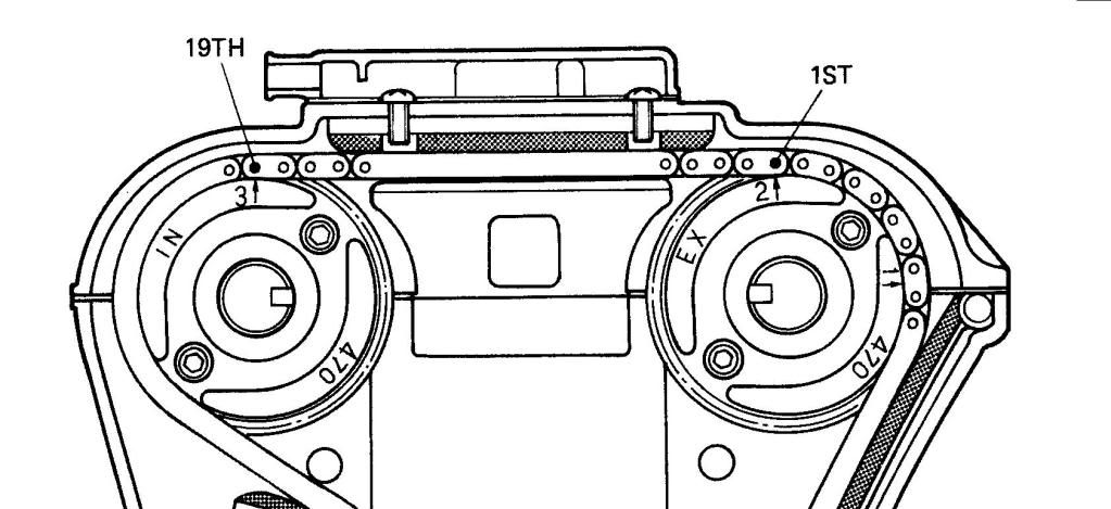
    Picture showing all three arrows lined up with motor at TDC. #1 seems off by a 1/2 tooth, but I think it's right and there are 19 pins between #2 arrow and #3 arrow. And tensioner is released and seems to be working OK.

    Next task is to check with degree wheel. That might take a few days to get to though.

    Comment


      #17
      Originally posted by chef1366 View Post
      That would work if you have the proper TDC found.
      Are you saying you are checking the clearance coming in and coming out of the shim?
      To answer your first question I would find the correct TDC by using a piston stop and taking degree wheel reading either side of TDC, halve these and adjust the degree wheel accordingly.

      Answer to second question is I would fit a narrow shim and using a feeler gauge rotate the motor until the feeler gauge will just fit between the lobe and shim, continue to rotate crank so the valve continues to open and then close and take a reading off the degree wheel as the cam is coming off the shim when the feeler gauge will just fit. Not perfect I know. A dial gauge would be better. But hopefully this will be close enough to tell me I am in the ball park and the cams are correctly fitted.

      Thanks Bill.

      Comment


        #18
        Hey Don,
        I think you have the timing correct, or as correct as you can get without slotting cam sprockets. Your own photo shows the #1 mark above the gasket surface so that may help provide some assurance that your position is correct.

        Ed

        To measure is to know.

        Mikuni O-ring Kits For Sale...https://www.thegsresources.com/_foru...ts#post1703182

        Top Newbie Mistakes thread...http://www.thegsresources.com/_forum...d.php?t=171846

        Carb rebuild tutorial...https://gsarchive.bwringer.com/mtsac...d_Tutorial.pdf

        KZ750E Rebuild Thread...http://www.thegsresources.com/_forum...0-Resurrection

        Comment


          #19
          Start that puppy up!
          1983 GS 1100E w/ 1230 kit, .340 lift Web Cams, Ape heavy duty valve springs, 83 1100 head with 1.5mm oversized SS intake valves, 1150 crank, Vance and Hines 1150 SuperHub, Star Racing high volume oil pump gears, 36mm carebs Dynojet stage 3 jet kit, Posplayr's SSPB, Progressive rear shocks and fork springs, Dyna 2000, Dynatek green coils and Vance & Hines 4-1 exhaust.
          1985 GS1150ES stock with 85 Red E bodywork.

          Comment


            #20
            Originally posted by chef1366 View Post
            Start that puppy up!
            Long way to go yet.

            Next job on the long list is pulling the carbs apart and giving them a good cleaning. Shimming the needles, float height, etc.

            Comment


              #21
              I am having second thoughts now after I read this in a Clymer Manual for the 550.


              What do you think.

              My #1 arrow was a mm or two above the joint surface.

              Comment


                #22
                Bloody 'ell Don - talk about conflicting messages. I reckon I'm right, but then I would wouldn't I?

                Having said that even Clymer wouldn't have written that if they weren't sure; it's probably easier to make a mistake on a diagram than it is with the written word, especially when it appears to have been written so precisely.

                In your photos I also noticed that those slots on the end of the cams didn't line up exactly, regardless of which position you engaged. That made me a tad nervous about my earlier thoughts as I've never seen them like that - maybe the 650 (which I've never owned) doesn't follow the Suzuki 'rule book'.

                You could start measuring things with a TDC probe / dial wheel etc and digging out your old school maths book - I think I'd be tempted to go down that route as a check of the Clymer setting.

                Ref your previous post about your carbs by the way....don't bother with any of that nonsense, just pop 'em on, fill up with fuel, start up and hit the red line as you pop a wheelie out of the garage
                79 GS1000S
                79 GS1000S (another one)
                80 GSX750
                80 GS550
                80 CB650 cafe racer
                75 PC50 - the one with OHV and pedals...
                75 TS100 - being ridden (suicidally) by my father

                Comment


                  #23
                  Originally posted by hampshirehog View Post
                  Ref your previous post about your carbs by the way....don't bother with any of that nonsense, just pop 'em on, fill up with fuel, start up and hit the red line as you pop a wheelie out of the garage
                  But don't I need to run it in.

                  Comment


                    #24
                    Originally posted by hampshirehog View Post
                    Bloody 'ell Don - talk about conflicting messages. I reckon I'm right, but then I would wouldn't I?

                    Having said that even Clymer wouldn't have written that if they weren't sure; it's probably easier to make a mistake on a diagram than it is with the written word, especially when it appears to have been written so precisely.

                    In your photos I also noticed that those slots on the end of the cams didn't line up exactly, regardless of which position you engaged. That made me a tad nervous about my earlier thoughts as I've never seen them like that - maybe the 650 (which I've never owned) doesn't follow the Suzuki 'rule book'.

                    You could start measuring things with a TDC probe / dial wheel etc and digging out your old school maths book - I think I'd be tempted to go down that route as a check of the Clymer setting.
                    Thanks HOG,

                    When I had the cams installed with the #1 arrow just above the upper head surface the notch in the end of the camshaft was pretty square to the head surface, but when it was one tooth the other way and the arrow was just below the upper head surface then that notch was on a definite angle, not level.

                    Just to add some more uncertainty I looked up the 550 and 650 manuals and they give differing link numbers between intake and exhaust cams. The 650E Manual gives it as 19 teeth and the 550 Manual gives it as 20 teeth. So going by this bit of info I could be spot on, 1 tooth or 2 teeth out on the sprockets.

                    It looks like it is back to "OLD SKOOL" engineering and digging the degree wheel out and trying to fathom via TDC which settings are right.

                    With my limited knowledge this could be fun. Just as well I've got some spare valves in the cupboard.

                    Thanks for your comments WALLY, they are all helpful.

                    Comment


                      #25
                      CHECKED The Degree on the Cams Today

                      Today I checked the degrees that each cam was opening and closing at and from that fathoming out the lobe centres for each shaft.

                      This degree checking was done with the cams in the first position in this post with the #1 arrow above the upper head surface and utilising 19 pins to the intake camshaft.

                      I could not use a dial gauge on this motor with it being an 8-valve, instead I used the feeler gauge method. I used a 2.25 shim in the bucket being measured and a .003" feeler gauge. I had approx 0.5mm clearance between cam lobe base and shim.

                      EXHAUST CAM:

                      Opens: 40 degrees BBDC
                      Closes: 14 degrees ATDC

                      40 + 180 + 14 = 234 degrees DURATION

                      234 / 2 = 117 - 14 = 103 degrees LOBE CENTER

                      INTAKE CAM:

                      Opens: 10 degrees BTDC
                      Closes: 46 degrees ABDC

                      10 + 180 + 46 = 236 degrees DURATION

                      236 / 2 = 118 - 10 = 108 degrees LOBE CENTER

                      __________________________________________________ ______

                      STANDARD CAM TIMING FOR THE GS650


                      __________________________________________________ ______

                      As most people seem to suggest that the lobe centres should be somewhere between 102 and 110 degrees then it would appear that I have the cams and chain pins in the correct positions. As one tooth on the cam sprocket by my reckoning is 12 degrees; 360 degrees divided by 30 teeth = 12 degrees.

                      The only problem seems to be that the cam Lobe Center numbers seem to be reversed as pointed out by RAPIDRAY in another of my threads. The exhaust cam usually has a higher number than the intake to allow for cylinder scavenging.

                      Obviously this reversed formation is the way it was designed, so not sure what to do now. Do I leave it this way with the exhaust on 103 and the intake on 108 degrees or slot the cam sprockets and set them at 104 intake and 106 exhaust as suggested by RAPIDRAY for for low down grunt.

                      Help please from all the knowledgeable guys on timing cams, RAPIDRAY, CHEF, etc.

                      Sorry about the Magna Carta & hope my calculations are OK. STEVE will soon let me know if they're not. He probably has this info on a SPREADSHEET somewhere.
                      Last edited by Guest; 04-08-2010, 08:15 AM. Reason: Corrected figure for duration, my maths was off.

                      Comment


                        #26
                        If it's only off by a degree or two from Ray's suggestion I'd call it done. Good work Don.
                        Ed

                        To measure is to know.

                        Mikuni O-ring Kits For Sale...https://www.thegsresources.com/_foru...ts#post1703182

                        Top Newbie Mistakes thread...http://www.thegsresources.com/_forum...d.php?t=171846

                        Carb rebuild tutorial...https://gsarchive.bwringer.com/mtsac...d_Tutorial.pdf

                        KZ750E Rebuild Thread...http://www.thegsresources.com/_forum...0-Resurrection

                        Comment


                          #27
                          Do you want to time this for a 650 or for a 550? Is the timing for a 650E the same as for a 650g? I only have a factory service manual for the G models which states the timing as your post shows. Even though the 650's share heads, the timing must be different since the cam gearing is different. Please don't take this as an insult to your approach, just trying to clarify it for my one curiosity

                          I did a little checking through my 550 shop manual, thanks BassCliff, and the 550 is timed a little differently than the 650 as you state. If you download the 550 manual it is on page 28. Sorry that I can't copy and paste a diagram like your post, but essentially it states that exhaust opens at 54 degrees before BDC and closes at 26 degrees after TDC. Intake opens at 26 BTDC and closes at 54 past ABdc. This gives an even 260 degrees of duration for both intake and exhaust timing.

                          I am not smart enough to figure these out, just trying to get some information out here so someone who is smart enough can get the answers for you.

                          Comment


                            #28
                            after you put them in time you need to "gently" turn the engine 720 degrees and see how they line up after. That is 2 complete crank turns. if you have it wrong you will feel resistance and that will be the indication to stop - and return to the begining. Also after the 2 turns if it is wrong the lines do not line up

                            You have it right in the first set of pix. The second way would probably just not rev up. 1 tooth off can be caught if you turn the engine over and over.

                            just think, they slapped these together on an assembly line going pretty fast.
                            SUZUKI , There is no substitute

                            Comment


                              #29
                              EXHAUST CAM:

                              Opens: 40 degrees BBDC
                              Closes: 14 degrees ATDC

                              40 + 180 + 14 = 243 degrees DURATION

                              234 / 2 = 117 - 14 = 103 degrees LOBE CENTER

                              Don, shouldn't this be:

                              243 / 2 = 122 - 14 = 108 degrees Lobe center

                              Comment


                                #30
                                Originally posted by waterman View Post
                                Do you want to time this for a 650 or for a 550? Is the timing for a 650E the same as for a 650g? I only have a factory service manual for the G models which states the timing as your post shows. Even though the 650's share heads, the timing must be different since the cam gearing is different. Please don't take this as an insult to your approach, just trying to clarify it for my one curiosity

                                I did a little checking through my 550 shop manual, thanks BassCliff, and the 550 is timed a little differently than the 650 as you state. If you download the 550 manual it is on page 28. Sorry that I can't copy and paste a diagram like your post, but essentially it states that exhaust opens at 54 degrees before BDC and closes at 26 degrees after TDC. Intake opens at 26 BTDC and closes at 54 past ABdc. This gives an even 260 degrees of duration for both intake and exhaust timing.

                                I am not smart enough to figure these out, just trying to get some information out here so someone who is smart enough can get the answers for you.
                                Ed the "G" and "E" camshafts are exactly the same as far as timing goes, it is only the number of teeth on the sprockets that is different.
                                Last edited by Guest; 04-05-2010, 09:40 PM.

                                Comment

                                Working...
                                X