.png "Powered by vBulletin")
Forgot to mention there is another way to do this and I prefer it with performance cams.
Find max lift with the dial indicator
Zero indicator
Turn motor backwards a bit, then forward and stop at .050" before max lift
Mark degree wheel
Roll motor past max lift stopping at .050" after
Mark wheel
1/2 way between the marks is your lobe center
Billy
-
 Guest replied
 -
Guest repliedHey Don, you sure do work fast, keeps me interested. I did check your math and you forgot to add 3 degrees to the 102 (1/2 total duration).....I came up with 105 centerline for the intake. Heres my mathOriginally posted by Suzuki_Don View Post
177 + 27=204(total duration)
divide by 2= 102
count 102degrees from the 3atdc
= 105 lobe center
Doesn't really matter .040" or .050" thats kind of splitting hairs.....BillyLeave a comment:
-
Guest repliedDecided to go outside and do a bit more.

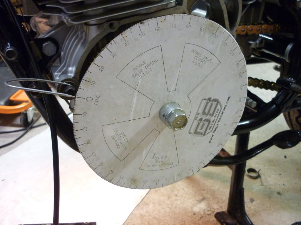
I set up the dial gauge and took readings off the degree wheel at .050" going down and then back up again. The readings that I got for the intake lobe on #1 cylinder was 3° after TDC and closing at 27° after BDC. So I came up with 102° lobe centre on the intake cam. A bit out from where it should be I would say.
Is .050" OK to do the readings at, or is .040" better.
Does someone want to check my calculations to make sure they are correct. Thanks.
I will do the exhaust tomorrow night hopefully.Last edited by Guest; 10-18-2010, 07:02 AM.Leave a comment:
-
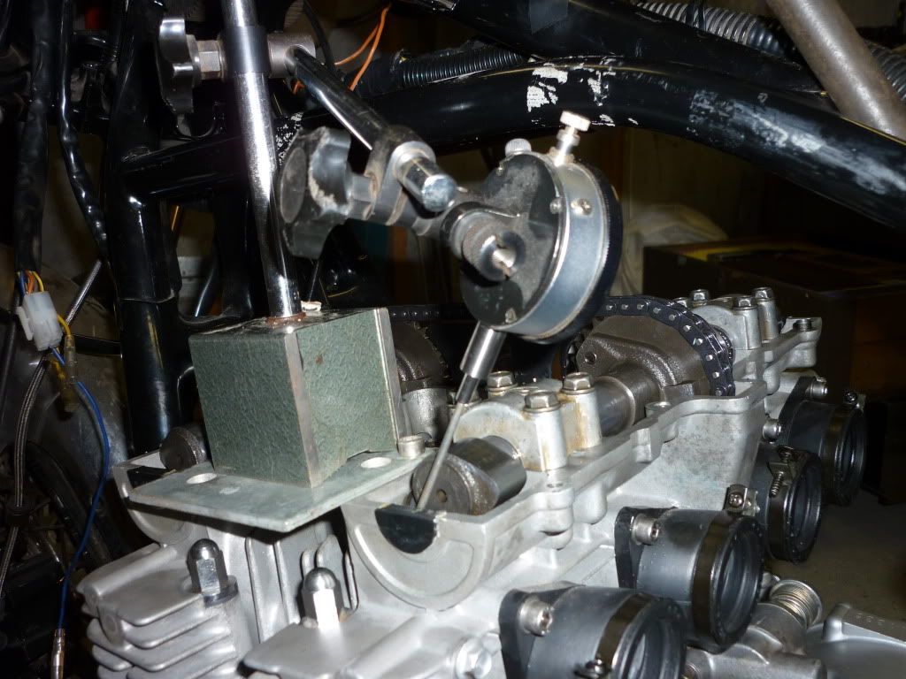
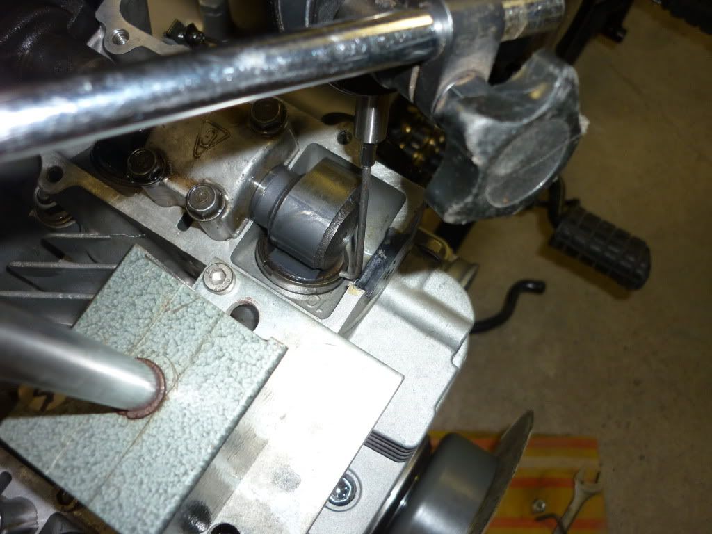
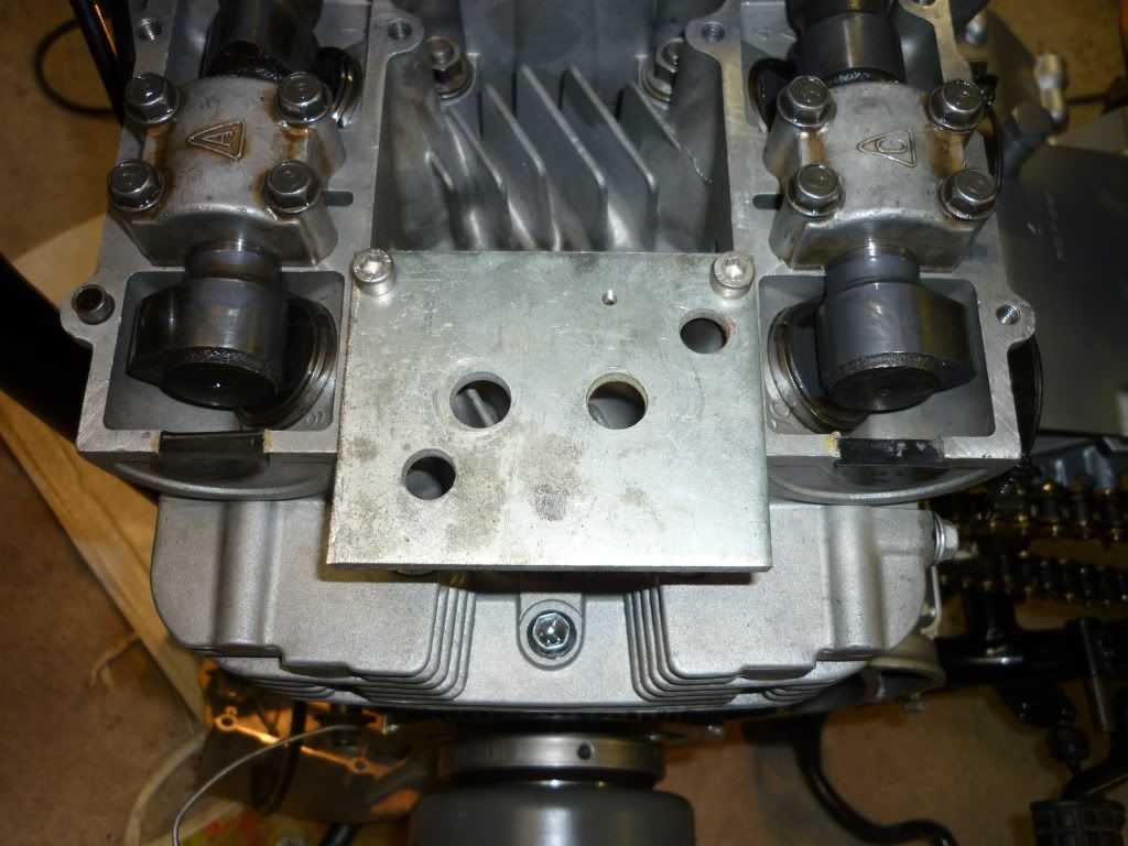
Guest repliedA bit more progress tonight.
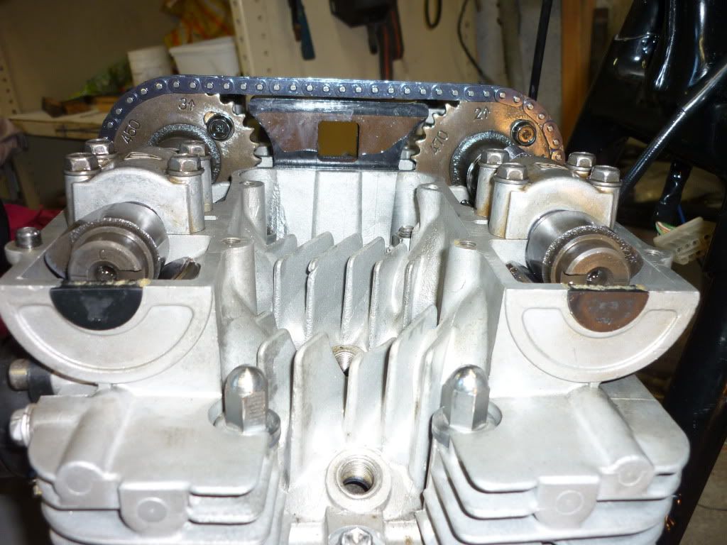
First the picture that Billy wanted of the ends of the camshafts.
Degree Wheel set up on one side of the motor.
TDC on other side of motor.
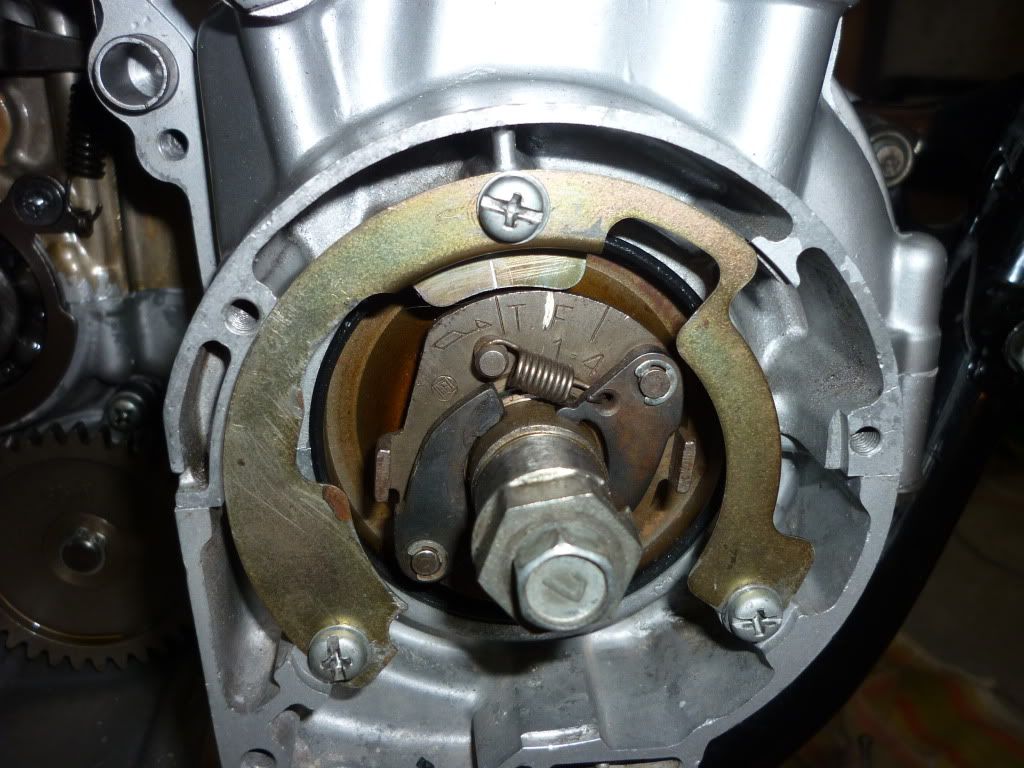
Metal plate set up for magnetic dial gauge.
.Leave a comment:
-
Guest repliedThanks for the compliment Billy. Just an 'ol amateur home made mechanic doing the best I can with a little help from my friends (you guys).Originally posted by BadBillyB View PostLeave a comment:
-
Guest repliedYes Ed they have the 34 tooth camshaft sprockets and 17 tooth crank sprocket as opposed to the 550 and 650e which have the 30 tooth cam sprockets and 15 tooth crank.Originally posted by Nessism View Post
Thanks for still working at it on my behalf though.Leave a comment:
-
Guest repliedHey Don, yeah I hear you. At least you will be more proficient at degreeing cams when you get done and like you said your already there, might as well. I use an aluminum 10" degree wheel and just super glue it to the left end of the crank with 0 somewhere near the top. Fasten the pointer wire nearby and find absolute TDC with a homemade piston stop. After setting the lobe centers, I just knock the degree wheel off the crank with my hand.Originally posted by Suzuki_Don View Post
If both cams are advanced the same amount (which they were) the valve to valve clearance stays the same, but the intake valve to piston clearance is closer. Since you have stock cams, theres lots of clearance there anyway. It's refreshing to see someone so thorough and clean with their engine build......BillyLeave a comment:
-
Don,
Noticed the 550 takes a 116 link cam chain while the 650 takes a 120 link chain. Which one did you use?
Edit: just noticed the 650E uses the same 116 link chain as the 550. Thought I was on to something but no. It's the 650G that takes a 120 link chain.Last edited by Nessism; 10-17-2010, 11:09 PM.Leave a comment:
-
Guest repliedOriginally posted by TeamDar View Post
OK thanks for that. I will report back when I have checked the lobe centres on my motor again.Leave a comment:
-
I like the 104-105 intake and the 105-106 exhaust. That will give you good mid-range where you will spend most of your time on a street bike. I think your timing will only be off about a degree at the crank. That is figuring about a 3" diameter cam sprocket with a circumference of 9.420". For every .026" in base gasket thickness difference the timing would change 1 degree at the cam or 2 degrees at the crank. Since you only changed .010" then it would be about 1/2 that or 1 degree at the crank. DarLeave a comment:
-
Guest repliedThanks Dar for raising this little issue, better to check it now before the motor is completely back together and deciding to do it then.Originally posted by TeamDar View Post
What are your suggestions on lobe centre settings for a street motor. Stock except for a 4 into 1 and fairly restrictive silencer.Leave a comment:
-
Guest repliedThanks Billy, I never could really visualise stuff with camshafts, always got confused when there were changes in the motor and people said that one cam advances and the other cam retards, yet to my way of thinking both cams are being pulled the same way by the chain off the crank sprocket and I would think that both cams are being advanced seeing as they are both moving either forward or backward by the same amount if you can see what I mean.Originally posted by BadBillyB View Post
But if my figures are truly going to be 102 and 108 then i can see a reason to degree the cams again. OH!! how I hate setting up that degree wheel and pointer on the crankshaft. Probably better to do it now while the generator cover is off.
I will set the shim clearances first and then check the lobe centres again after that.
If the lobe centres are at 102 and 108 is there any chance the valves will hit the piston or each other. I have read that the lower the numbers the closer things run to each other.Leave a comment:
-
Don, see if the noise goes away. If it does then take the time to degree the cams again. DarLeave a comment:
-
Guest repliedHey, alright....I am probably wrong this time, my old eyes dont see detail very good.....I think you will find the cam timing is only advanced 1 or 2 crankshaft degrees with the taller base gasket. The intake timing will be a smaller number (TDC to max lift) and the exhaust number will be a larger number (max lift to TDC) .......I'm not a street tuner but that seems like a lot of advace for an intake cam.....Now we are talking 102/108 I/E.....BillyOriginally posted by Suzuki_Don View PostLeave a comment:
Leave a comment: