1982 GS750T - R/R Connector Help Required...

Collapse
X
 
  • Time
  • Show
Clear All
new posts
  • pdqford
    Forum Mentor
    Past Site Supporter
    Super Site Supporter
    • May 2015
    • 379
    • Central NY State

    #31
    My bad! I just found the wiring diagram for the T, so I'm going to modify my previous post.
    I surly didn't mean to make this even more complicated by trying to revise my previous post, but here goes.

    Originally posted by pdqford
    Okay Sam, thanks for that video.

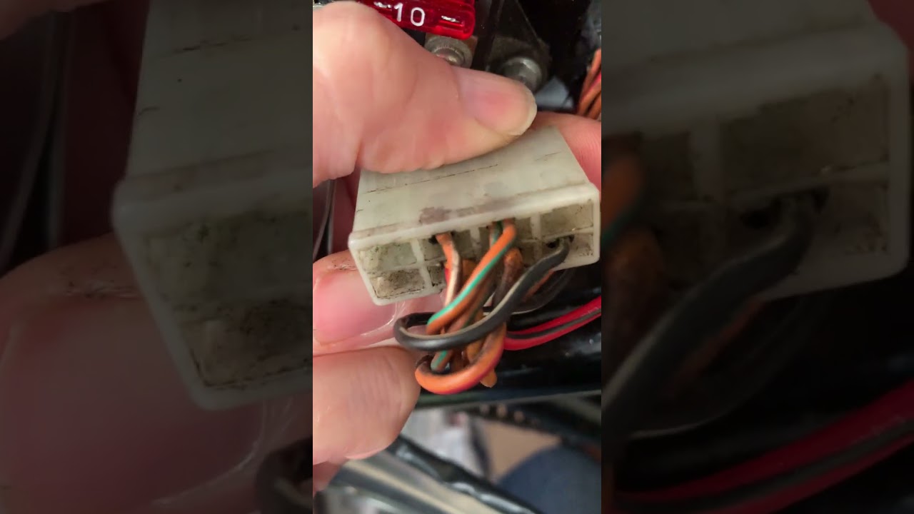
    One thing I am not sure about is why your white 6-pin R/R connector wires are different from the picture Rich posted of his white 6-pin R/R connector wires. Don't you both have T's?

    Based on this pin-out of a 6 pin connector:


    it appears to me that the typical pin layout of a 6-pin R/R puts the three stator wires together, while the other three pins represent the R/R power out pin, the R/R ground pin, and the R/R sensing pin. So the yellows from the stator go to the lower three pins of the R/R.

    That leaves us with those upper three pins on the R/R. And the B/Y looks to be the ground.

    I suspect the two red wires represent the power wire out and the sensing wire.

    So here is how I believe the the other red wires (three of them!) function.

    The smaller red wire that connects to your battery + post and goes into the main harness carries power to the fourth fuse down (labeled MAIN) in your fuse block.
    (I don't know why it is a 10A fuse as it originally was a 15A fuse.) That MAIN fuse feeds power thru a red wire that goes up to the ignition switch. When the ignition switch is turned on, an Orange wire brings power back to the fuse block and powers the top 3 fuses (which were originally 10A fuses).

    I assume the R/B wire that you show going from the fuse box to the center pin on your white connector and then into the center pin of the R/R is powered by the MAIN fuse so that the R/R can monitor system voltage. (I'm not sure that it is a good idea for the R/R sensing wire to be powered all the time - even with the bike off).

    To prove this out, break out your ohm meter and put one probe on the R/B wire (your WIRE TWO) going from the fuse block to the center pin of the white connector and the other probe on the red wire that connects to the battery + post.. I would expect continuity, ergo: the R/R sense the system voltage! (all the time?)

    The final red wire (the one you referred to as WIRE ONE) that goes from the upper left pin of the connector into the main harness is the R/R power out wire from the R/R. Within the main harness that power out wire is spliced into the red wire that goes from the MAIN fuse to the ignition switch (described above). That allows the R/R to supply power to the ignition switch (and the vehicle electrical load) and/or a convoluted path back to the battery + post to charge the battery.

    To prove this out, break out your ohm meter. Connect one probe to the smaller red wire that connects to the battery + post and the other probe to the power out wire from your white connector. Should always show continuity.

    So that's how I figure the PO had the bike wired. No guarantees !
    Hopefully it will make it easier for you to go from the current wiring to the one that Nessium reccomends.

    And I hope someone will come along and check to see if I maybe I made some wrong assumptions.
    Jim, in Central New York State.

    1980 GS750E (bought used June,1983)
    1968 CB350 Super Sport (bought new Oct,1968)
    1962 CA77 305 Dream (bought used Feb,1963)

    Comment

    • SamLack99
      Forum Apprentice
      Past Site Supporter
      Super Site Supporter
      • May 2023
      • 99
      • Dawlish, Devon, UK

      #32
      To prove this out, break out your ohm meter and put one probe on the R/B wire (your WIRE TWO) going from the fuse block to the center pin of the white connector and the other probe on the red wire that connects to the battery + post.. I would expect continuity, ergo: the R/R sense the system voltage! (all the time?)
      With the ignition switch off = No continuity
      With the ignition switch on = Continuity


      The final red wire (the one you referred to as WIRE ONE) that goes from the upper left pin of the connector into the main harness is the R/R power out wire from the R/R. Within the main harness that power out wire is spliced into the red wire that goes from the MAIN fuse to the ignition switch (described above). That allows the R/R to supply power to the ignition switch (and the vehicle electrical load) and/or a convoluted path back to the battery + post to charge the battery.

      To prove this out, break out your ohm meter. Connect one probe to the smaller red wire that connects to the battery + post and the other probe to the power out wire from your white connector. Should always show continuity.
      With the ignition switch off = Continuity
      With the ignition switch on = Continuity

      Thank you, Jim =)

      What I'm concluding from this is:

      Red wire (one) will go into the R/R
      Red/Black wire (two) is going to be removed.

      So...

      ...The wires for the two connectors that go into the replacement SH775 R/R.

      Connector 1 (Grey) will get the three yellow wires from the stator​
      Connector 2 (Black) will get the black/yellow wire (four) and Red wire (one)

      Now then, do I need to put a 30amp fuse inline on the Red wire (one)?

      And if yes, can anyone recommend a simple way to put a 30amp fuse inline on Red Wire (one)?

      Thank you =)


      Comment

      • dgates1
        Forum Mentor
        Past Site Supporter
        Super Site Supporter
        • Jun 2024
        • 363
        • Arlington, TX

        #33
        That should be fused through your main fuse on the block. But like pdqford mentioned, usually larger than 10amp.

        Could test by doing continuity on that line again and take out the fuse to see if that breaks it.
        - David
        80 GS850GL, 82 GS1100G
        Arlington, TX
        https://visitedstatesmap.com/image/ARMNMTNDSDTXsm.jpg

        Comment

        • pdqford
          Forum Mentor
          Past Site Supporter
          Super Site Supporter
          • May 2015
          • 379
          • Central NY State

          #34
          Originally posted by SamLack99

          Now then, do I need to put a 30amp fuse inline on the Red wire (one)?
          ;
          Well, the factory didn't use an extra fuse in that red wire. It goes up into the harness and is spliced into the red wire that runs from fuse MAIN to the ignition switch.
          So power out from the R/R can go two ways. The power can go from the splice up to the ignition switch, and with the ignition switch on the power will come back down the orange wire and feed the top three fuses in the fuse box. And/or the power can go from the splice back to the fuse box, back thru the MAIN fuse and on to the battery.

          You can probably remove the fuse box and pop the back off to see what wires go to which fuse, just in case the PO changed anything.

          If you decide to add an in-line fuse, 30A is way too big. A short would probably melt some wires before the fuse blows. Again, the factory used a 15A fuse in the MAIN fuse. I don't know but I suspect the charging system would struggle to put out 15A.

          Hopefully one of the electrical guys like Nessism or David will come by and verify.
          Last edited by pdqford; 10-30-2024, 01:09 PM.
          Jim, in Central New York State.

          1980 GS750E (bought used June,1983)
          1968 CB350 Super Sport (bought new Oct,1968)
          1962 CA77 305 Dream (bought used Feb,1963)

          Comment

          • SamLack99
            Forum Apprentice
            Past Site Supporter
            Super Site Supporter
            • May 2023
            • 99
            • Dawlish, Devon, UK

            #35
            Ah, I see.

            I hadn't understood that the power went through the fuse box (eventually).

            So a 15Amp fuse in the Main slot 'should' take care of it.

            Got some time off work coming up soon, and I'm looking forward to investing it in putting Suzy back together and seeing if she'll start.

            I'll keep you posted =)

            Thanks again everyone!

            Comment

            • Rich82GS750TZ
              Forum Guru
              Past Site Supporter
              Super Site Supporter
              • Jun 2018
              • 5632
              • Mifflinburg, PA / Land of Tar & Chip

              #36
              Point of clarification. My pics of a six (actually 8) pin connector are what is connected to the bottom of the fuse box and in no way should they be confused with what Sam had going into his SH555-12 RR. My confusion still lies in Sams pics seem to show no wires in this connector where mine show 2 reds.


              Last edited by Rich82GS750TZ; 10-30-2024, 06:55 PM.
              Links

              Comment

              • SamLack99
                Forum Apprentice
                Past Site Supporter
                Super Site Supporter
                • May 2023
                • 99
                • Dawlish, Devon, UK

                #37
                Good point Rich,

                Tomorrow, I'll get a picture of the wires going into the connector that goes into my fuse box.

                I'd do it now, but it's way past my bedtime =)

                Comment

                • pdqford
                  Forum Mentor
                  Past Site Supporter
                  Super Site Supporter
                  • May 2015
                  • 379
                  • Central NY State

                  #38
                  Just an FYI, on BikeCliff's website, page 66 of the GS750ET service manual has the wiring diagram for the GS750T(Z).
                  Jim, in Central New York State.

                  1980 GS750E (bought used June,1983)
                  1968 CB350 Super Sport (bought new Oct,1968)
                  1962 CA77 305 Dream (bought used Feb,1963)

                  Comment

                  • Rich82GS750TZ
                    Forum Guru
                    Past Site Supporter
                    Super Site Supporter
                    • Jun 2018
                    • 5632
                    • Mifflinburg, PA / Land of Tar & Chip

                    #39
                    Here it is…………….
                    Links

                    Comment

                    • SamLack99
                      Forum Apprentice
                      Past Site Supporter
                      Super Site Supporter
                      • May 2023
                      • 99
                      • Dawlish, Devon, UK

                      #40
                      Here's a video of the wires going into the connector that connects to my fuse box...


                      I just noticed, I have two cables going into the orange/green slot. Huh?

                      Comment

                      • Rich82GS750TZ
                        Forum Guru
                        Past Site Supporter
                        Super Site Supporter
                        • Jun 2018
                        • 5632
                        • Mifflinburg, PA / Land of Tar & Chip

                        #41
                        Everything there looks same as mine, but your 2 empty slots on the right where I have 2 reds. If I get a chance tomorrow, I will trace them to where they go to/come from exactly, If I can do it without tearing everything apart. My Tiger is down at the moment, and the weather is just too nice to be without a bike.
                        Last edited by Rich82GS750TZ; 11-01-2024, 02:03 PM.
                        Links

                        Comment

                        • pdqford
                          Forum Mentor
                          Past Site Supporter
                          Super Site Supporter
                          • May 2015
                          • 379
                          • Central NY State

                          #42
                          Since your wiring has been modified by the PO, you don't necessarily need a red wire going to the fuse box.

                          The PO may have taken that 2nd red wire from your battery positive post, that went to a bullet connector down near the electrical panel, unplugged it, and connected it to the red wire that goes up to the ignition switch (since the + side of the ignition switch is hot all the time, even from the factory).

                          When the ignition switch is turned on, power comes back down the orange wire to power up the top three fuses of the fuse block. Where that orange wire enters the fuse box is where the PO picked up the sensing voltage for the old regulator. That way the sensing wire going into the old regulator is only powered up when the ignition key is on.

                          Since this is only a guess, so to verify, where does that 2nd wire from your battery + post end up?
                          Jim, in Central New York State.

                          1980 GS750E (bought used June,1983)
                          1968 CB350 Super Sport (bought new Oct,1968)
                          1962 CA77 305 Dream (bought used Feb,1963)

                          Comment

                          • SamLack99
                            Forum Apprentice
                            Past Site Supporter
                            Super Site Supporter
                            • May 2023
                            • 99
                            • Dawlish, Devon, UK

                            #43
                            Originally posted by pdqford
                            Since your wiring has been modified by the PO, you don't necessarily need a red wire going to the fuse box.

                            The PO may have taken that 2nd red wire from your battery positive post, that went to a bullet connector down near the electrical panel, unplugged it, and connected it to the red wire that goes up to the ignition switch (since the + side of the ignition switch is hot all the time, even from the factory).

                            When the ignition switch is turned on, power comes back down the orange wire to power up the top three fuses of the fuse block. Where that orange wire enters the fuse box is where the PO picked up the sensing voltage for the old regulator. That way the sensing wire going into the old regulator is only powered up when the ignition key is on.

                            Since this is only a guess, so to verify, where does that 2nd wire from your battery + post end up?
                            Hey Jim,

                            I'll see if I can find out tomorrow. Should be fun =)

                            Comment

                            • salty_monk
                              Forum LongTimer
                              GSResource Superstar
                              Past Site Supporter
                              Super Site Supporter
                              • Oct 2006
                              • 14013
                              • London, UK to Redondo Beach, California

                              #44
                              The 555 is a Mosfet but not a series RR. Like a lower power version of the FH012 that everyone moved to before we learnt about the SH775 I think. The Elektrex you see in the Post is long out of business. They were a US company that made parts for Harley's it just so happened that they had one RR that worked well for the GS.

                              What you see in the UK is either just coincidence or someone trying to take advantage of the name....
                              1980 GS1000G - Sold
                              1978 GS1000E - Finished!
                              1980 GS550E - Fixed & given to a friend
                              1983 GS750ES Special - Sold
                              2009 KLR 650 - Sold - gone to TX!
                              1982 GS1100G - Rebuilt and finished. - Sold
                              2009 TE610 - Dual Sporting around dreaming of Dakar..... - FOR SALE!

                              www.parasiticsanalytics.com

                              TWINPOT BRAKE UPGRADE LINKY: http://www.thegsresources.com/_forum...e-on-78-Skunk/

                              Comment

                              • GSXR7ED
                                Forum LongTimer
                                Past Site Supporter
                                Super Site Supporter
                                • Dec 2012
                                • 10159
                                • DE via L.A.

                                #45
                                Sub'd for future reference.
                                GS750TZ V&H/4-1, Progressive Shocks, Rebuilt MC/braided line, Tarozzi Stabilizer[Seq#2312]
                                GS750TZ Parts Bike [Seq#6036]
                                GSX-R750Y (Sold)

                                my opinion shouldn't be taken as gospel or in any way that would lead you to believe otherwise (30Sep2021)

                                Comment

                                Working...