-
 Guest repliedKool_aid kid, where do you get these bimetal breaker/fuse's at, sounds like a good safe guard for anyones system, at least worth a try. Thanks JD
 -
SERIES_RR_Size.jpg
here are some nominal dimension; teh SH775 is with a trimmed shroud and no mating connector.
Leave a comment:
-
Are you really dead-set on getting the Compufire or would you like a similar R/R that costs about half as much?
The cheapest that I have seen a (new) Compufire sell for is about $150. The SH775 R/R from Polaris can be bought for about $70, plus shipping.
Both of those replacements are a bit bigger than stock. The Compufire is just a bit larger footprint, but considerably taller. The Polaris is a considerably larger footprint, but about the same height. Either one might need a little fabrication to mount it, and might even need a new location.
.Leave a comment:
-
Guest repliedJust got in from pushing my bike 5 miles home; my rectifier burned up today, about to order the compufire R/R. I saw a warning on watching the heat - will I have the same problem with it trying to melt like my old one?Leave a comment:
-
Generally it is not the wire itself but the connections and crimps. You will expect as much as 1 volt dropped through the ignition switch (if it is dirty and with all the wire), but it is the drops between R/R and battery that are really bad for the battery charging voltage.Leave a comment:
-
Guest repliedI have a question on all this, I've read through everything and I think I have a good grasp and understand why things are they way they are. But when I checked voltage drop with a multimeter I had .5v from the bullet connector coming out of the harness into the ignition key switch. As far as I know there is no other contacts so that says the wiring has the resistance built in. Now will this show up in case of bad grounds or is this wire just degraded?Leave a comment:
-
Thank you Posplayr - I do appreciate your thorough, concise response and direction. Thanks for not getting too theoretical on me - it took a few times reading this as it was... Makes sense to me now, especially when compared to the SPG on the ground side. I can wrap my head around that.
I'll tap the bit from the R/R into the harness at the "T" and add that fuse between there and the battery, checking/cleaning connections and will solder/wrap any new connections and check voltage drop before and after as well as resistance and call it good for now!Leave a comment:
-
The answer to the Questions:
A.) At the battery yes, but more specifically between the battery and the "T" , because the "T" is really the point that brings the two sources together ( battery and R/R output). If you short anything connected to the "T" a lot of current will try and flow from the battery, through the "T" to wherever the short is. That fuse limits that current to a safe level so the the wiring in the harness will not melt.
The R/R output doesn't need to be fused here as it is fused down stream in each of IGNITION, HEADLAMP,SIGNAL. The real reason for the main battery fuse is in case the R/R shorts, it is directly across the battery and you will have a fire.
B.) Yes you Tap off of the "T" for all currents. In contrast If you tap off of the battery +, then all of the R/R current has to run from the R/R(+) to the battery (+) and then go on to it's final load. That means the full R/R current (15 amps) has to all run between the R/R(+) and the Battery(+) to get to the load. That creates the biggest voltage drop possible for a given about of connector resistance.
If you pull current from the "T", then the current from "T" to battery (which includes fuse box and big bullet connector) only carries 3-4 amps maximum with a corresponding drop in the voltage drops meaning the battery voltage will be closer to the R/R output voltage.
The construction of the "T" on the positive side, is basically the same as a Single Point Ground on the ground side. It minimizes the sharing of currents, by splitting the currents as close to the source or return as possible. This avoids sharing of currents.
In the case of the "T" it is no sharing of load current with charging current between battery and R/R. You will have to study the examples and ask specific questions about them, because my answers are going to get more theoretical which probably doesnt help.
There is nothing really mysterious, you just have to understand the splitting of currents and the desire to reduce the current between battery and R/R so that the voltage drops are less.
This is what the revised Phase A is trying to minimize.
enstLast edited by posplayr; 08-05-2014, 12:26 AM.Leave a comment:
-
Wait - I want another stab at it.
I love it, you're like the Zen Master at the top of a mountain where a mortal, non-technical noob like me scales the top to ask a question that to them is difficult and when posed to the Master, he returns with deeper, even more technical questions as his answers! Helping us understand the deeper meaning behind all of this!
So I'll take a stab at it;
A.) where do you put the fuse to protect the bike from the battery shorts? At the battery?
B.) where do you tap off from the battery R/R to power the rest of the bike. At the "T"? The part "battery R/R" has me confused...
Help men Zen Master Pos, enlighten me or kick me off the mountain?Leave a comment:
-
-
I think you have your self a little confused. The R/R is always in parallel to the Battery in either case. It it is not then you will never charge the battery. The question is
A.) where do you put the fuse to protect the bike from the battery shorts and
B.) where do you tap off from the battery R/R to power the rest of the bike.
The OEM way and the one I recommend is the only one where the current flowing between the battery and R/R is only charging current. That minimizes voltage drops keeping your battery charging at the highest voltage possible.
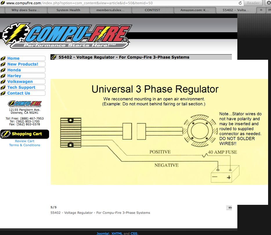
The compufire drawing ignores how you power the bike. It looks good on the surface but it is "too simple"Leave a comment:
-
What about the fuse?
Me too. That's what I am going to do, I have been reading various PosPlayr posts and I noticed you hadn't heard back yet here either. I'd also like to know if it is recommended to fuse it, or keep it like the original R&R was, which wasn't fused. Either way, I will wire it as close to the harness "T" as possible, not down by the connector to the OEM R&R.
For me it was the nice inline fuse holder (albeit with no lid or cap!) and this:
And I went to the battery directly since the R&R charges the battery, well that and runs the rest of the electrical system. I assumed that a better charged battery that also acts as a buffer/sort of capacitor to smooth the spiky voltage from the R&R was the place from which the electrical system draws its power, and less voltage drop/current loss from the R&R to the battery would provide the best case scenario...Stator>R&R>battery>fuse box>electrical loads, but I failed to consider that the R&R also provides power directly to the bike while running via the "T" and if we go to the battery directly then it all has to go through the main fuse then to the loads, stressing the fuse box and possibly leaving us stranded.
Best if the R&R connects back into the main harness to provide the power to the bike and charge the battery with what's left, and as long as the connections are all clean and the SPG method is used, there should be ample power left to charge, right?
My concern is what buffers/smooths the voltage from the R&R in this scenario and what about protection from a short to ground? I blew a whole bunch of LED's when my original R&R kicked the proverbial bucket...Does the battery somehow buffer it as well since it's connected through the T? I don't understand how. Perhaps the FET based power from the Compufire is clean/smooth enough that we don't worry about spikes, but what if it shorts to ground? What will protect the rest of the system, or keep the smoke from exiting the wires?
Should we be using that fancy fuse that came with the R&R in-line to the red wire harness or just wire it direct? It was a 40Amp fuse, I changed it out to a 20Amp, as 40 I'm told is way too much.Leave a comment:
-
Guest repliedJim has been talking about this for some time. He convinced me so I changed back from direct battery feed to the stock Suzuki feed for the Compu-Fire. To tell the truth I did not notice any difference so I'm wondering why I went directly to the battery in the first place. It must have been the nice inline fuse holder that confused the issue.Leave a comment:
-
Guest repliedSO this is news to me. I had my Compufire wired directly to the battery.
So I should pare back my negative wire on my Compufire as short as possible to the battery negative terminal.
I should then connect the positive wire on my Compufire to the original red wire that connected the OEM reg\rect?Leave a comment:
-
Leave a comment: