• Required reading for all forum users!!!

    Welcome!
    Register to access the full functionality of the GSResources forum. Until you register and activate your account you will not have full forum access, nor will you be able to post or reply to messages.

    A note to new registrants...
    All new forum registrations must be activated via email before you have full access to the forum.

    A Special Note about Email accounts!
    DO NOT SIGN UP USING hotmail, outlook, gmx, sbcglobal, att, bellsouth or email.com. They delete our forum signup emails.

    A note to old forum members...
    I receive numerous requests from people who can no longer log in because their accounts were deleted. As mentioned in the forum FAQ, user accounts are deleted if you haven't logged in for the past 6 months. If you can't log in, then create a new forum account. If you don't get an error message, then check your email account for an activation message. If you get a message stating that the email address is already in use, then your account still exists so follow the instructions in the forum FAQ for resetting your password.

    Have you forgotten your password or have a new email address? Then read the forum FAQ for details on how to reset it.

    Any email requests for "can't log in anymore" problems or "lost my password" problems will be deleted. Read the forum FAQ and follow the instructions there - that's what we have one for...

  • Returning Visitors

    If you are a returning visitor who never received your confirmation email, then odds are your email provider is blockinig emails from our server. The only thing that can be done to get around this is you will have to try creating another forum account using an email address from another domain.

    If you are a returning visitor to the forum and can't log in using your old forum name and password but used to be able to then chances are your account is deleted. Purges of the databases are done regularly. You will have to create a new forum account and you should be all set.

Installing an Eastern Beaver fuse box.

Steve

GS Whisperer
My son's '80 1000G had a minor meltdown on the way home from Flori-duh just before Christmas, so I decided that this was the time to finally pull the trigger and order some new fuseboxes for all of us.

I had been looking around for some time and decided that the box from Eastern Beaver would be best for our bikes.

Although the quality of the EB wiring harnesses are top-notch (I have one for the stator-to-R/R), I decided to not get them and make my own harness. This would allow me to do a custom install, instead of trying to work around what was given to me.

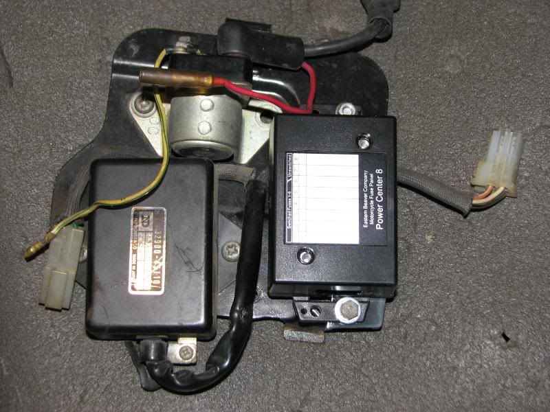
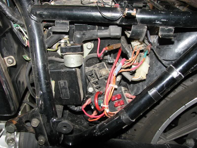
One of the previous owners had had problems with the fusebox and had wired in another fuse panel.
Pulled the side cover and this is what was there.
IMG_0064.jpg


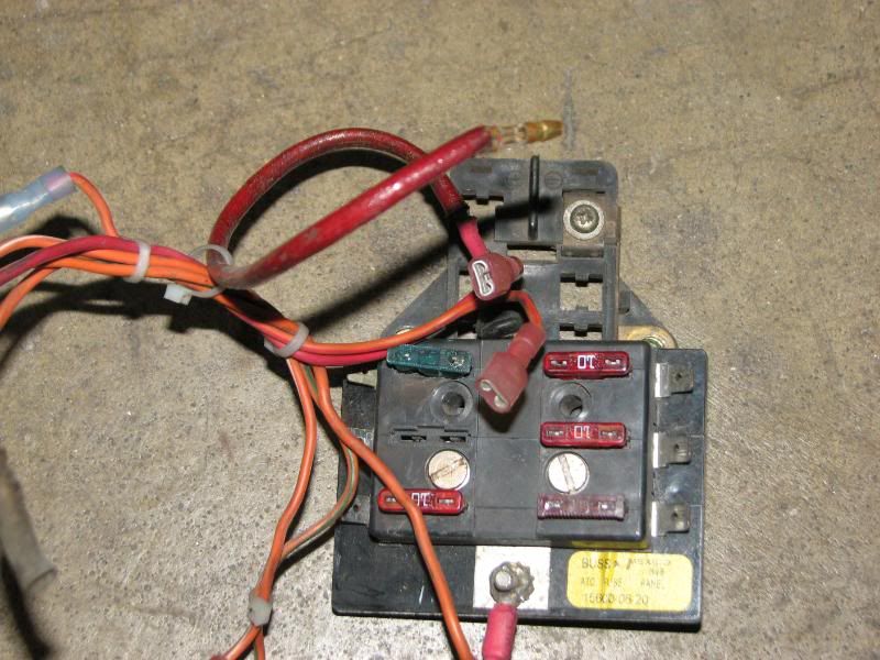
I removed the fuse panels from the bike.
IMG_0066.jpg


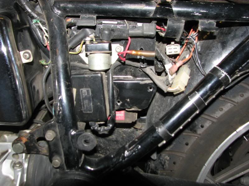
For some reason, the second panel was just piggy-backed onto the gutted original panel.
IMG_0067.jpg


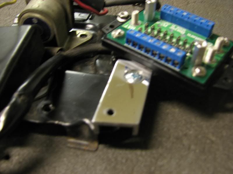
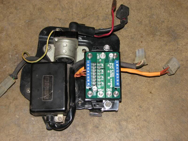
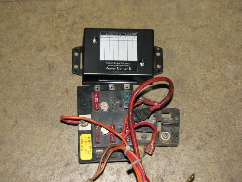
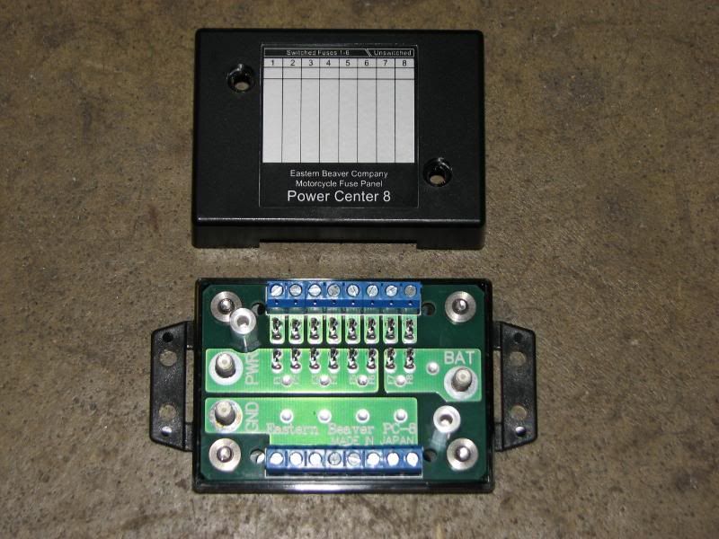
Here is a size comparison of the new Eastern Beaver box to the original(s).
IMG_0070.jpg


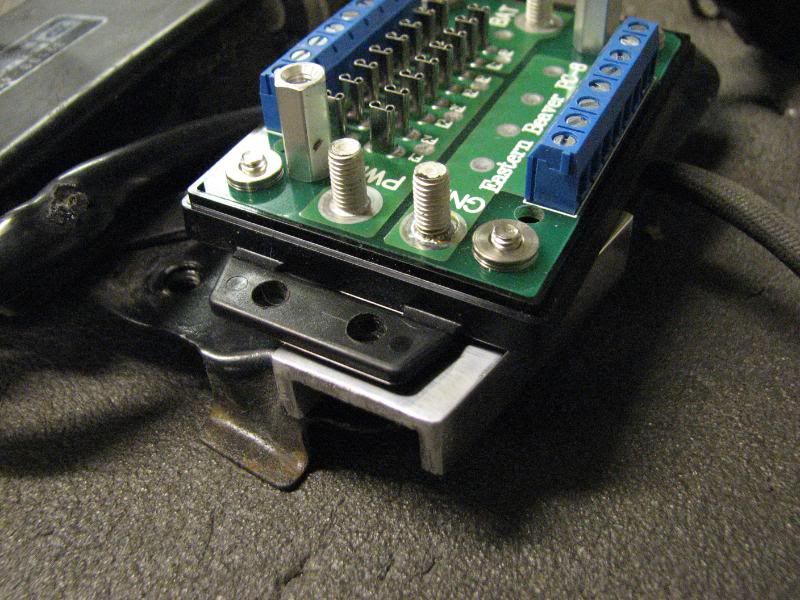
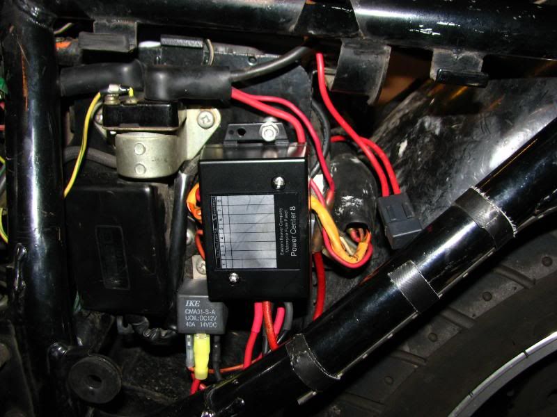
First peek inside the new box.
IMG_0071.jpg


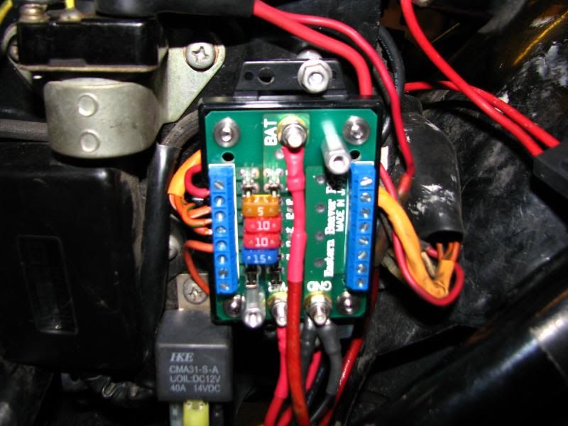
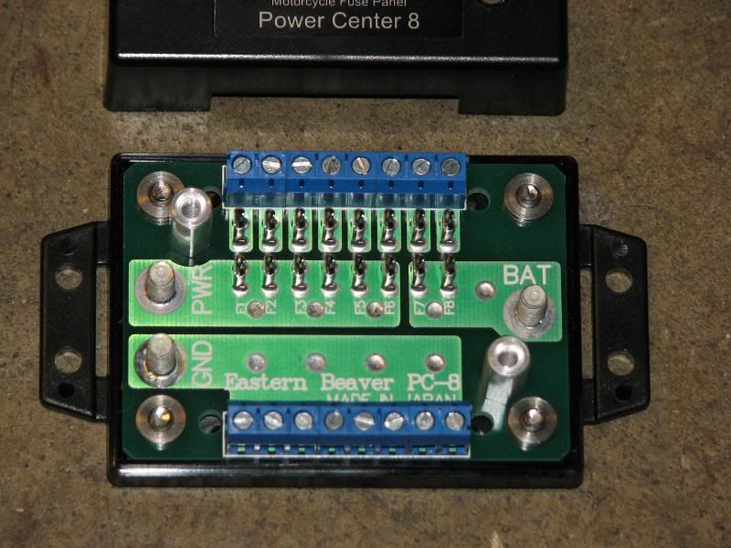
Getting a bit closer. Very nicely laid out.
The two fuse positions in the upper right will provide unswitched power.
The other six positions will provide switched power.
There are eight ground screws available, but can't imagine using them all.
IMG_0077.jpg


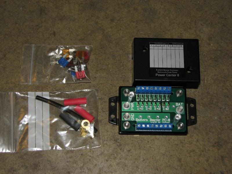
Here is what you get in the basic fuse panel kit. Included are several fuses of varying capacity, terminals and heat-shrink tubing for the input wires and mounting hardware.
IMG_0078.jpg


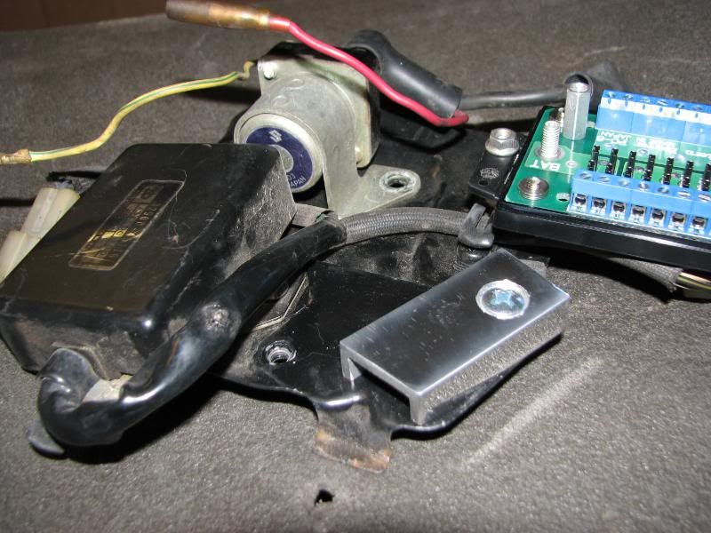
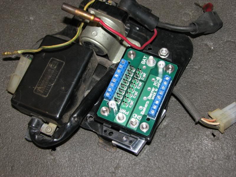
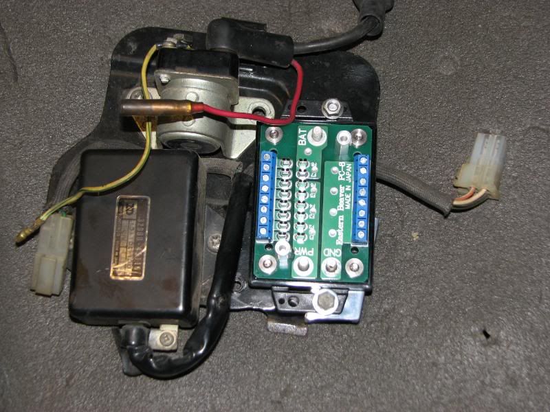
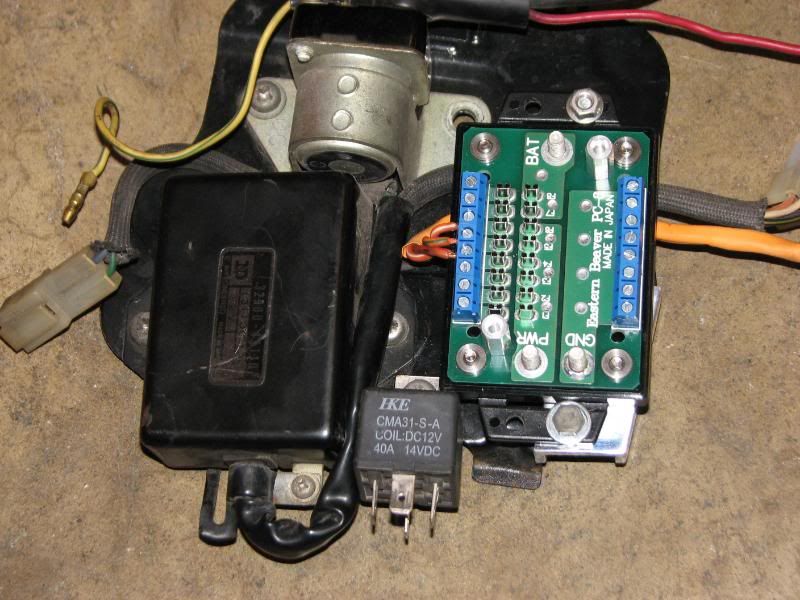
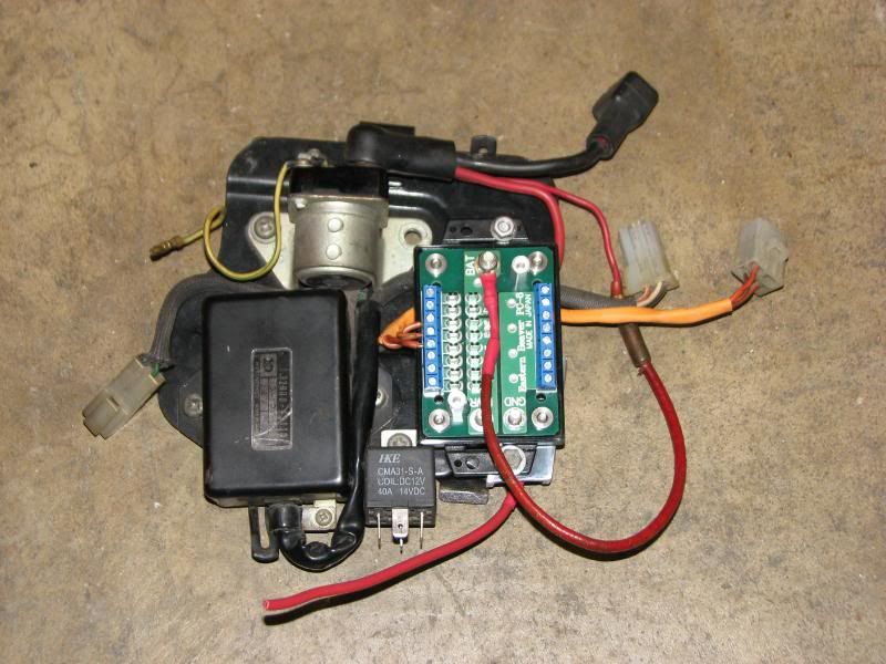
I removed the panel on the side of the battery box that holds the fuse panel, ignitor and starter solenoid to make things easier.
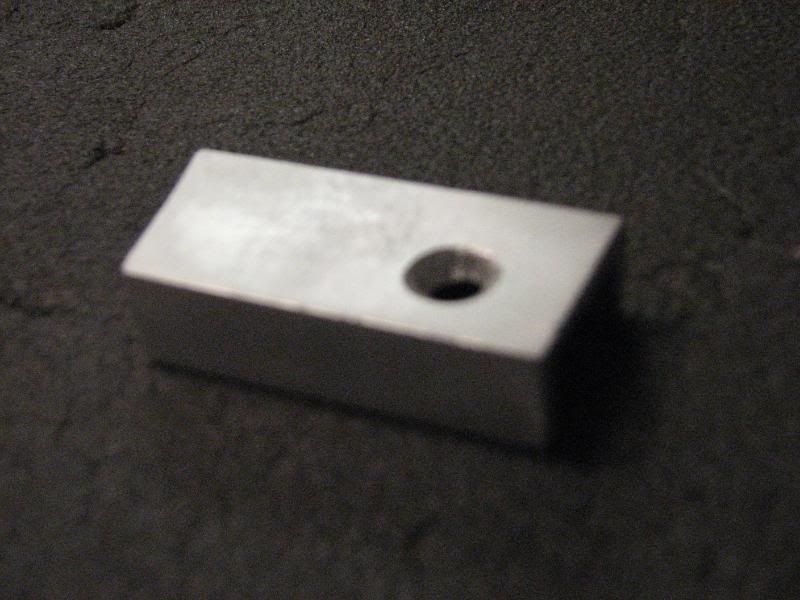
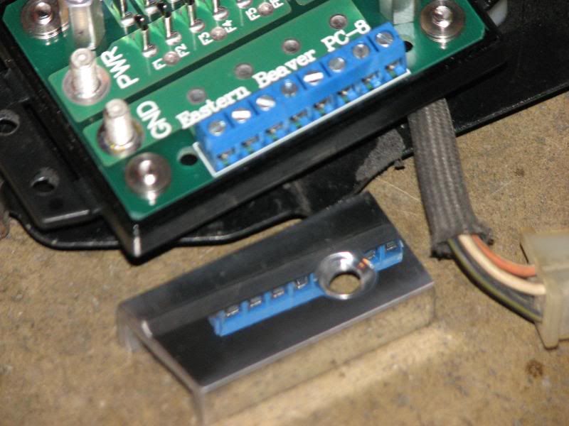
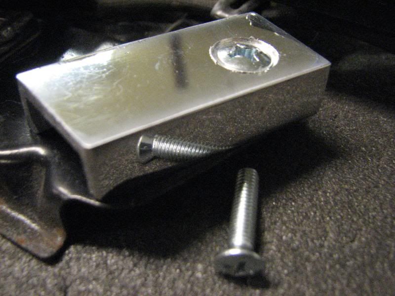
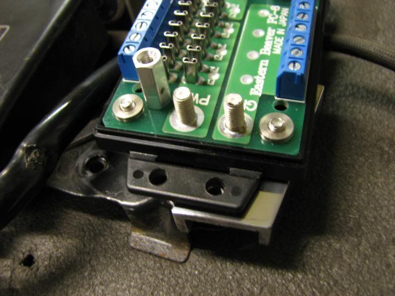
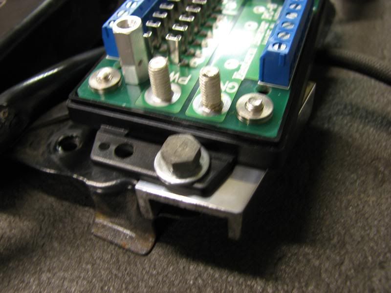
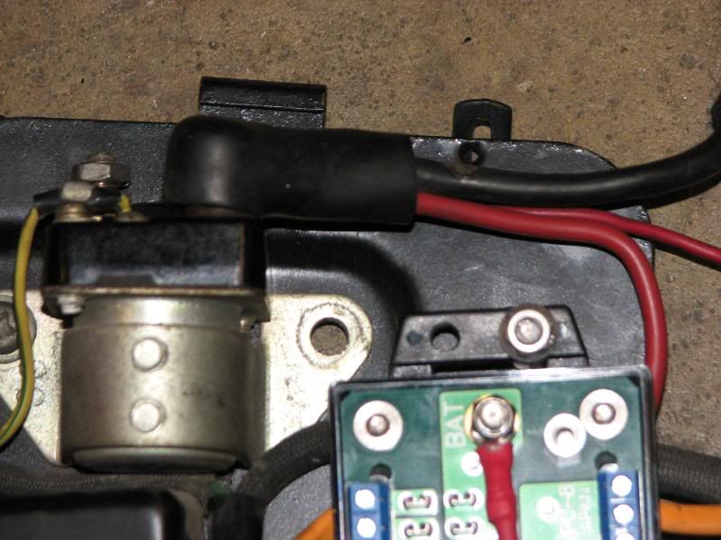
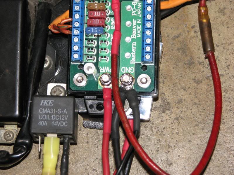
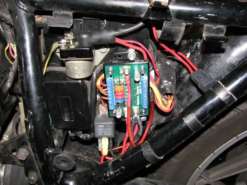
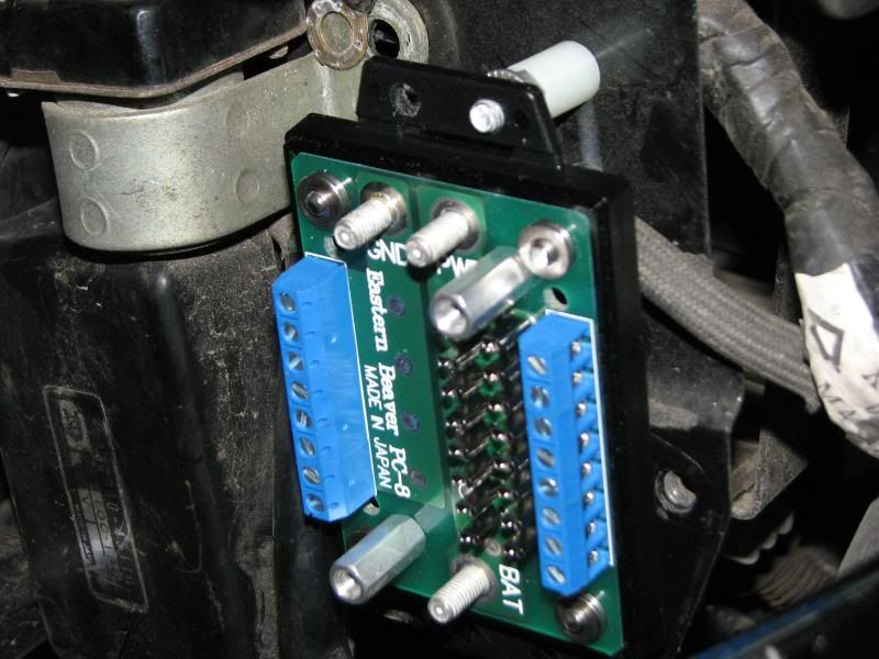
I continuied by mounting the top of the box. Because there are some wires running behind my intended location, the panel needs to be spaced a bit from the mounting panel. There was an unused hole in the panel above the original fuse panel. You can see half of it peeking out behind the connector on the red wire in the second picture. I came from behind with a 5mm bolt, a 1/2" nylon spacer and a flanged nut, then cinched it down tight.
IMG_0082.jpg


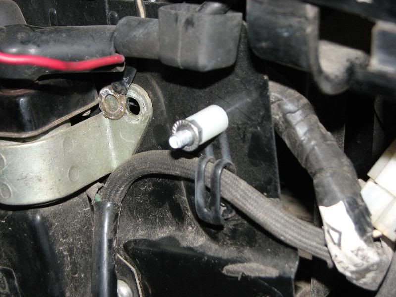
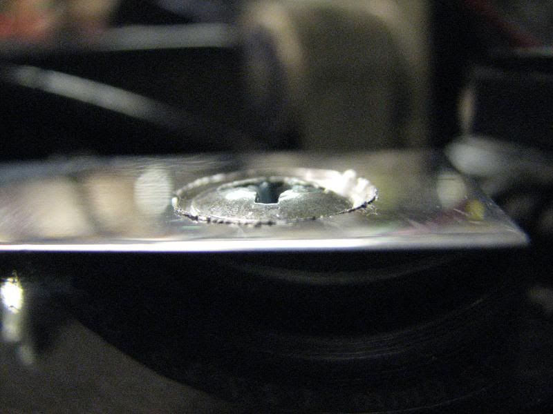
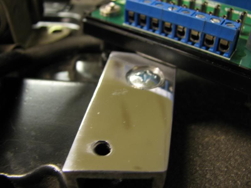
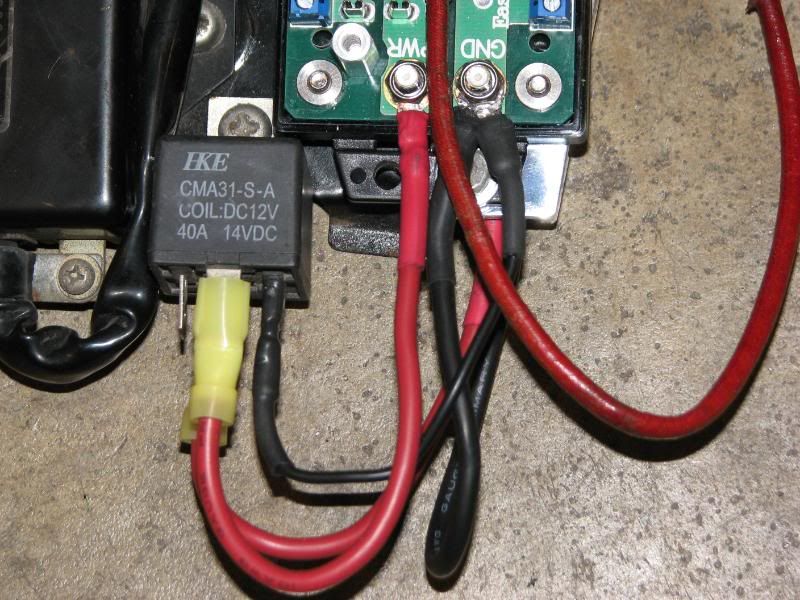
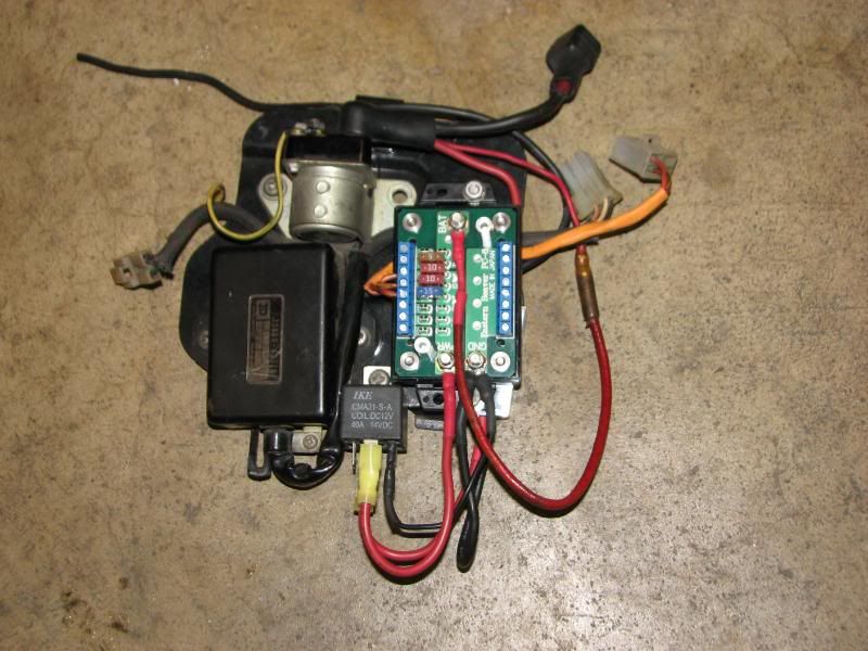
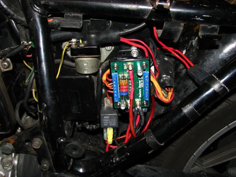
Had to drill out the mounting hole to fit the 5mm bolt, but it fits very well.
IMG_0081.jpg


.
 
Last edited:
The bottom of the panel also needed to be spaced out away from the mounting panel, but the holes didn't line up, so an adapter was needed. Scrounging through my miscellaneous metal box, I found some channel extrusion that fit perfectly. With a bit of measuring, I cut it to what I thought might fit, and drilled a hole to mount it to the mounting panel. I used one of the holes that held the stock fuse panel. Since the new fuse panel will sit directly over this channel, I countersunk the hole for a flat-head screw.
IMG_0086.jpg


Dang it, it happened again!
Somehow, whenever I have a piece of aluminum in my hand, I seem to trip. I usually manage to hang on to it, but it gets DANGEROUSLY close to my buffing wheel.
IMG_0090.jpg


Just testing the fit on the panel and making sure the countersink is deep enough.
IMG_0091.jpg


Yep, looks like it will work.
IMG_0092.jpg


Sorry, just can't resist. Yeah, I know it's not going to be seen again, but I have fun doing it.
IMG_0094.jpg


Testing the fit at the bottom of the fuse panel.
IMG_0098.jpg


Making sure it lines up, then marked and drilled the hole for mounting.
IMG_0099.jpg


Sorry, lost the close auto-focus on the camera, but here is the hole.
IMG_0100.jpg


Hard to tell from this shot, but, since the channel is relatively thick, I just tapped the hole for a 5mm screw.
IMG_0102.jpg


One final check to make sure it still lines up.
IMG_0103.jpg


.
 
Here is the screw (bolt) that holds it in place. Keeping everything metric, so it takes an 8mm wrench.
IMG_0104.jpg


Checking the mounted panel to make sure it looks relatively straight.
IMG_0105.jpg


One more check, but with the cover installed, giving a preview of the finished project.
IMG_0108.jpg


I had cut the original wires from the stock fuse panel, then connected them to the new panel.
I tinned the ends of the wires before clamping them into the new panel.
I then ran the wires in the space behind the fuse panel, out to where they would join the wiring harness in pretty much the stock location.
IMG_0109.jpg


I mounted my relay in the second hole that held the original fuse panel.
IMG_0112.jpg


I used the starter solenoid terminal (battery side, of course) to get my power for the relay, using 10 gauge wire..
There was already a wire there that powered the stock fuse panel, I used that for my unswitched power in the new panel.
IMG_0117.jpg


Ran the new wire through the boot, along with the battery wire, to maintain a clean, covered connection.
IMG_0119.jpg


Here, the unswitched wire is connected to the BAT terminal, the power wire to the relay is waiting for its new terminal.
IMG_0121.jpg


.
 
Last edited:
OK, a bit has happened here. The power wire is connected to #30 on the relay, the switched wire is connected to #87, then run to the PWR terminal on the fuse panel and ground wires are connected. There is a 10 gauge wire running from the GND terminal on the board to the battery and a smaller wire from the GND terminal to #86 on the relay.
IMG_0122.jpg


Moved the view down a bit, to see more of the wires at the bottom of the relay.
IMG_0123.jpg


An overall view of the preliminary wiring. Time to put it back in the bike.
IMG_0124.jpg


Mounted the larger panel back in the bike and connected a few more wires. If you look closely, you can see the small orange wire going to the bottom of the relay. That is the original wire that comes back from the ignition switch to power the rest of the stock fuse panel. I am using it to trigger the relay (terminal #85). The small red wire that has been added to the fuse panel is the original wire that went from the MAIN fuse to the ignition switch. It is connected here through a small fuse on the unswitched side. There is another orange wire that is now connected to the left side of the fuse panel. This is the sense wire from the R/R. Should get a GOOD reference signal here. You will also notice another fuse holder to the right of the new panel. The R/R had been connected straight to the battery, with no fuse. :eek:
IMG_0125.jpg


One last close-up. Still one unswitched and two switched fuses available for him to add his accessories. We will work on those later today.
IMG_0131.jpg


Looks a bit better than the first picture, eh? :-k
IMG_0132.jpg


Still have to add the accessories, but here is where most will call it "finished". :D
IMG_0136.jpg


.
 
Hi,

Very nice work, as usual, Mr. Steve. Thanks for writing it all up for us and sharing your expertise. May I put it in a PDF and keep it in a safe place?

All the best to you and yours,

Cliff
 
Hi,

Very nice work, as usual, Mr. Steve. Thanks for writing it all up for us and sharing your expertise. May I put it in a PDF and keep it in a safe place?

All the best to you and yours,

Cliff
I am going to re-write it into more of a tutorial style then get it to you, Cliff. :cool:

.
 
Steve, do you plan to discuss the circuits and fuse considerations? Maybe one or two of the standard charging system alterations? That took some study on my part when I replaced my fuse panel.
 
I am assuming the inline 30A fuse for the Battery that comes with the EB Harness is pretty unnecessary for the GS application?
 
I am assuming the inline 30A fuse for the Battery that comes with the EB Harness is pretty unnecessary for the GS application?
I have no idea how the EB harness is wired, I did my own wiring. However, I can assume that the fuse is between the battery and the relay.

In the stock wiring scheme, current flows from the battery, through the MAIN fuse, through the ignition switch, through the individual circuit fuses, then on to their respective loads. With the EB setup, I am guessing that current will flow from the battery, through a 30 amp fuse, through the relay, through the individual circuit fused, then on to their respective loads. The only real difference is that the stock setup has a manually-operated switch (the ignition key), the EB setup uses an electric switch (relay) that uses the manually-operated switch to control it.

I am guessing that your question is mainly concerning the necessity of the fuse. Personally, I would keep it. There is a rather remote possibility that the relay can fail and short out. That could melt your harness, the fuse would prevent that. If you are questioning the use of a 30, when the stock MAIN fuse is 15, remember that EB is selling generic kits to cover most models of most bikes, not specific kits. Besides, if you look at the current draw, it gets close. The coils draw about 3.5 amps each, the headlight is about 5 amps, the other lights will add up to another 4 or 5 amps. That's almost 20 amps just to keep it going down the road. Add in the occasional use of brake light (3 amps) or turn signal (5 amps, when ON), you can see why the charging system is at its limit.

How does the stock setup get away with only having a 15 amp fuse? Simple. When the bike is running the power is supplied by the R/R, not the battery. The only fuses between the R/R and the individual loads on the bike are the circuit fuses. When the bike is running, the MAIN fuse is only handling current that is charging the battery, which will only be the few amps that are leftover that the bike is not using.

.
 
Sorry, I guess I should have clarified. I understand what you did and why the fuse is in the pre built harness. I was more wondering why you never put one in? Do you feel it is too excessive?
 
The stock MAIN fuse is inbetween the R/R and the battery. My bike has been re-wired to have the R/R go straight to the battery, instead of the "T" connection in the stock harness. There is a fuse in that "direct" line, so I did not feel one was necessary between the battery and the relay.

Yes, that is counter to what I said earlier. I don't always do what I preach. I preach what I feel is "correct", but might "do" what I feel I can get away with. :oops:

.
 
I was thinking of running the R/R ground through the + side of the board and fusing it that way . Or fusing the relay through the second battery space?
 
I was thinking of running the R/R ground through the + side of the board and fusing it that way . Or fusing the relay through the second battery space?
You do NOT want to ground the R/R through the + side of ANYTHING. :eek:
The R/R ground wire should go rather directly to the battery - terminal or to a very good frame ground, which then goes straight to the battery terminal.


If I am understanding what you are trying to do, you will be running a wire straight to the fusebox, then out of one of the two unswitched terminals, you will feed the relay that will then feed the rest of the terminals? Too much wiring, to complicated.

You really only need a large fuse between the R/R and the battery, if your R/R is wired directly to the battery. If that is the way you have it wired, you can run a wire straight from the battery to the BAT terminal in the fusebox (unswitched). From one of the two fuses on that unswitched terminal, run the red wire to the ignition switch. Use the orange wire that comes back from the ignition switch to activate the relay. The output of the relay will connect to the PWR terminal on the fusebox to power the other 6 fuses.

Your bike will take 3 of those 6 fuses to run LIGHTS, SIGNALS and IGNITION, as usual, leaving 3 switched, fused terminals for accessories. You also have one unswitched fuse at the top that is perfect for connecting your battery tender.

.
 
Steve the reason for the main fuse is so that the battery does not see a short. The only reason for having an in line fuse between the r/r and the battery is because if you hooked the r/r directly to the battery you would be in danger of shorting the battery because you have violated the rule to have any connection to the battery (+) be fused.

Bottom line is that it is quite dangerous to have anything connected to the battery that is not fused. That is one of the reasons why the "t" is the preferred "hot point".

But in that configuration, the output of the R/R connects to the "T" point, then all the way up to the ignition switch (red) and back to the fuse block (orange), without fuses. Only the 'branch' circuits are protected after that.

What protects the R/R from a short in the ignition switch wiring?
 
But in that configuration, the output of the R/R connects to the "T" point, then all the way up to the ignition switch (red) and back to the fuse block (orange), without fuses. Only the 'branch' circuits are protected after that.

What protects the R/R from a short in the ignition switch wiring?

The stator is only capable of providing 15 amps (through the r/r rectification process) which is only slightly more that what it takes to run the bike. So if you are going to fuse the output of the r/r you need to be able to tell if it is for a normal load 14 amps or a bad short load that is going to exceed the 15 amps that the r/r can source. Not easy to figure out what is a good load and a bad load so there is no fuse protecting the R/r output from shorting. I don't think any is nesessary as there would be no conditions that I could see the fuse blowing with a short where you are not running the risk of blowing the fuse under normal operations and as suffering all the attendant risk of those outcomes.
 
Back
Top