Announcement

Collapse
No announcement yet.

Degreeing Camshafts -- Information Required

Collapse
X
 
  • Filter
  • Time
  • Show
Clear All
new posts

    #61
    More help needed on camshaft numbers

    This is the progress so far.

    I decided to pull the cams again and lop the ends off the #1 cyl end of the cams. Too hard to degree them otherwise.

    The pictures tell the story.


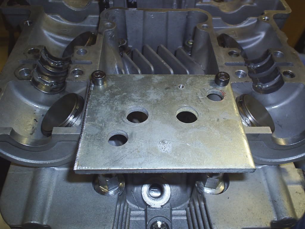
    The plate I made up to mount the magnetic dial gauge base to. Turned out to be very solid and did the job very well.


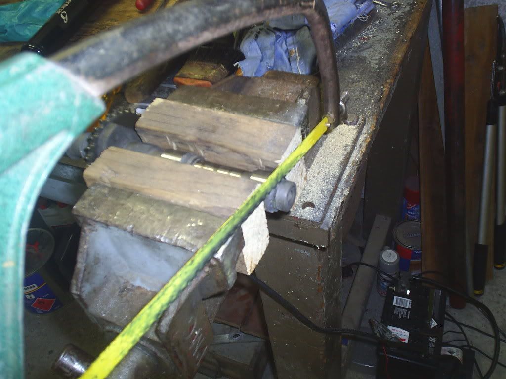
    Didn't have a chop saw so the old hacksaw had to suffice. did the job OK. Only about 10 minutes for each cam.


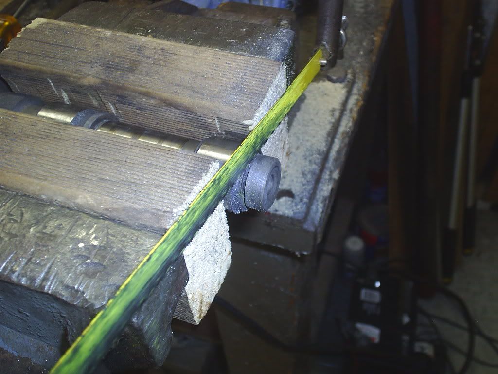
    Another close up of cutting process.


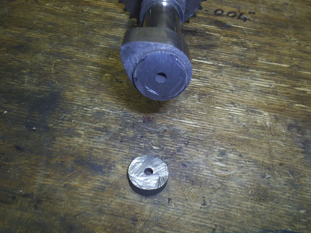
    End result after end had been cut off the camshaft.


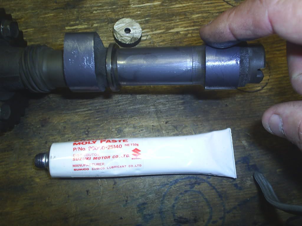
    Cam lobes and bearing surface being lubed with moly prior to reassembly.


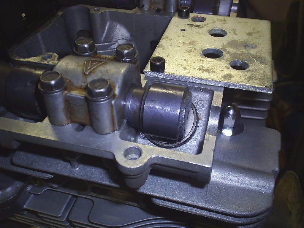
    Cam reinstalled with greater distance between the end of cam and where the half moon seal goes.


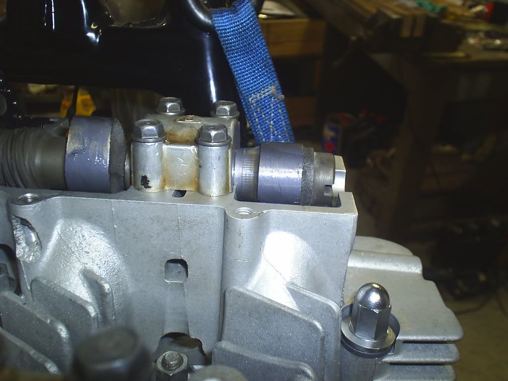
    This pic shows the other end of cam with smaller clearance with half moon seal area for comparison.


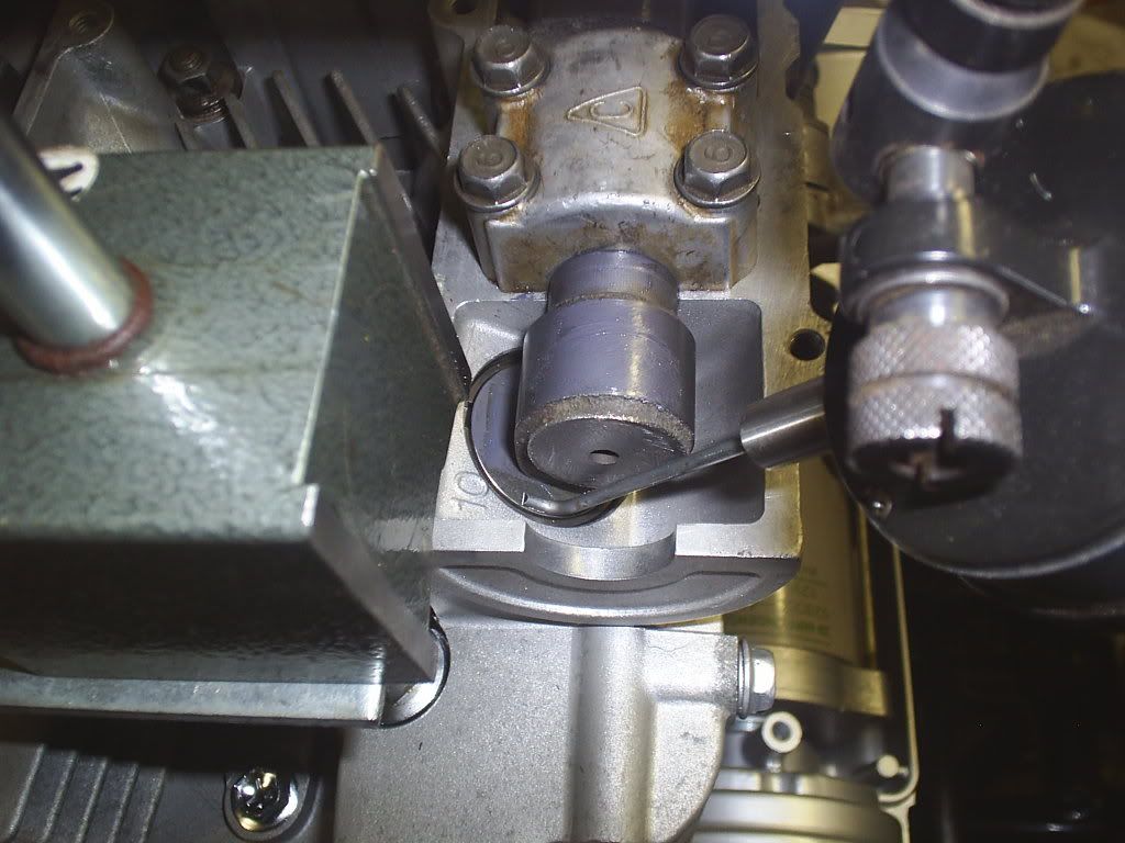
    The end result shows plenty of room for the dial gauge probe to fit on bucket/shim.


    SEE QUESTION NEXT POST !!!!!!!

    Comment


      #62
      This is the question that must be answered for me to go to the next step

      I degreed the Intake cam first. And the numbers were as follows:

      Intake Opens @ 2 degrees BTDC and
      Intake Closes @ 32 degrees ABDC

      This gave me a Lobe Center of 105 degrees

      __________________________________________________ __________

      Then I did the exhaust cam and this is where I struck trouble.

      Exhaust Opens @ 31 degrees BBDC and
      Exhaust Closes @ 1 degree BTDC (this figure is usually ATDC)

      The rule generally is that you add the opening and closing numbers to 180 and divide by two and subtract the smaller number of the opening and closing numbers.

      Well normally you subtract an opening number that is after TDC, but my figure of 1 degree is BTDC, so I am not sure if I need to subtract that number or add it in the equation.

      HELP!!!!!!!!!!!!!

      Please

      If someone wants to work out my exhaust Lobe Centers for me, then go right ahead.

      It will be appreciated as always.


      Thanks

      Comment


        #63
        they are both 105 from your information.

        31+1+180=212

        212 X 0.5=106 - 1= 105..

        doesn't matter BBDC or ABDC the readings all count in the equasion.
        SUZUKI , There is no substitute

        Comment


          #64
          The exhaust cam lobe center is 106 degrees. The cam did not rotate 212 degrees it only went 210 degrees. 31+179=210. The cam did not rotate the 180 degrees between BDC and TDC. It was -1 degree from TDC. When this happens you add the TDC number to 1/2 the duration.
          210 divide by 2=105
          105+1=106
          Last edited by TeamDar; 04-17-2010, 04:27 PM. Reason: because

          Comment


            #65
            Sorry Don just got home from work.
            Looks like it's been answered.
            1983 GS 1100E w/ 1230 kit, .340 lift Web Cams, Ape heavy duty valve springs, 83 1100 head with 1.5mm oversized SS intake valves, 1150 crank, Vance and Hines 1150 SuperHub, Star Racing high volume oil pump gears, 36mm carebs Dynojet stage 3 jet kit, Posplayr's SSPB, Progressive rear shocks and fork springs, Dyna 2000, Dynatek green coils and Vance & Hines 4-1 exhaust.
            1985 GS1150ES stock with 85 Red E bodywork.

            Comment


              #66
              Originally posted by chef1366 View Post
              Sorry Don just got home from work.
              Looks like it's been answered.
              Yes Bill, but you can't get out of it that easy. You will notice there are two different answers, so I am waiting on you to verify for me. You have done your cams a few times and I bet other peoples as well.

              What were some of the figures you came up with. Did you ever get an exhaust cam closing BTDC.

              Comment


                #67
                Exhaust lobe centerline is 106 degrees BTDC.

                Intake lobe centerline is 105 degrees ATDC.
                Ed

                To measure is to know.

                Mikuni O-ring Kits For Sale...https://www.thegsresources.com/_foru...ts#post1703182

                Top Newbie Mistakes thread...http://www.thegsresources.com/_forum...d.php?t=171846

                Carb rebuild tutorial...https://gsarchive.bwringer.com/mtsac...d_Tutorial.pdf

                KZ750E Rebuild Thread...http://www.thegsresources.com/_forum...0-Resurrection

                Comment


                  #68
                  You must be using a large lift reference in order to get the BTDC number instead of ATDC. Try using .030" and your numbers will make more sense, especially with stock cams.

                  Comment


                    #69
                    Drawing a diagram helps too.

                    Exhaust centerline is measured in degrees before TDC
                    Intake centerline is measured in degrees after TDC

                    Nice website with on-line calculator here... http://www.rbracing-rsr.com/camshaft.html
                    Ed

                    To measure is to know.

                    Mikuni O-ring Kits For Sale...https://www.thegsresources.com/_foru...ts#post1703182

                    Top Newbie Mistakes thread...http://www.thegsresources.com/_forum...d.php?t=171846

                    Carb rebuild tutorial...https://gsarchive.bwringer.com/mtsac...d_Tutorial.pdf

                    KZ750E Rebuild Thread...http://www.thegsresources.com/_forum...0-Resurrection

                    Comment


                      #70
                      Originally posted by TeamDar View Post
                      You must be using a large lift reference in order to get the BTDC number instead of ATDC. Try using .030" and your numbers will make more sense, especially with stock cams.
                      I am using .040" with standard size shims for the bucket. I can try .030" and that should be enough to move it past TDC.

                      Thanks

                      Comment


                        #71
                        Originally posted by Nessism View Post
                        Drawing a diagram helps too.

                        Exhaust centerline is measured in degrees before TDC
                        Intake centerline is measured in degrees after TDC

                        Nice website with on-line calculator here... http://www.rbracing-rsr.com/camshaft.html
                        Thanks ED.

                        As you said in the previous post I have 105 on the intake and 106 on the exhaust with the dial indicator. I did not have to change the sprocket positions from the setup that I had done using the feeler gauge method. So it is good to know that method works if you do not have a dial gauge available or you do not want to hack off the end of your camshaft.

                        So the 105 & 106 is close enough for me. I know Ray said 2 degrees difference, but I am sure it will be better than it was originally at 103 exhaust and 108 intake.

                        Comment


                          #72
                          Finally finished and all bottoned up

                          Well I have done the final degreeing for the cams and the results as they stand are 105 degrees for the intake and 106.75 for the exhaust. I could not get things any better than that. The sprockets kept moving as I was tightening up the sprocket bolts. It's only out by 1/4 degree so I guess that's not too bad.

                          I rebuilt the camchain tensioner and refitted it.

                          I then rechecked the shims and changed a couple. So they are all around .08 now. I ran into one small problem when removing the shims and that was that I could not use the Suzuki tool to depress the valve buckets on the exhaust and intakes for #1 cylinder. This was because I had cut the ends off the cams and the tool had nothing to bear on to perform this task.

                          So I had to resort to the zip tie method which I had not used before and was very surprised at it's ease and the amount it held the valve off it's seat. Actually made it easier to remove the shim as it created extra clearance at the top of the bucket.

                          The carbs are the next thing on the agenda for this project. Separated them last night and will pull them down individually tonight and prepare them for cleaning. Was surprised by the amount of cobwebs in them.

                          I need to change the jets in them as they are BS32mm for the 650G which has richer jetting than the 650E model. The spec table calls for #97.5 main jet, do you think that one size larger would hurt things. I thought I would put #100 mains in place of the #110s that are in there now and shim the needles by .040" as well.

                          Do you think I should come down a size or two on the pilot air jet to make it a bit richer in that department as well.
                          Last edited by Guest; 04-21-2010, 11:22 PM.

                          Comment


                            #73
                            I'd start with the larger main and work from there with plug readings.
                            1983 GS 1100E w/ 1230 kit, .340 lift Web Cams, Ape heavy duty valve springs, 83 1100 head with 1.5mm oversized SS intake valves, 1150 crank, Vance and Hines 1150 SuperHub, Star Racing high volume oil pump gears, 36mm carebs Dynojet stage 3 jet kit, Posplayr's SSPB, Progressive rear shocks and fork springs, Dyna 2000, Dynatek green coils and Vance & Hines 4-1 exhaust.
                            1985 GS1150ES stock with 85 Red E bodywork.

                            Comment


                              #74
                              Originally posted by chef1366 View Post
                              I'd start with the larger main and work from there with plug readings.
                              So Bill are you saying don't shim the needles till I do plug chops. Just try and get hold of #100 main jets and go from there.

                              I also notice that the starter jet on the 650G (which is the set of carbs I have) is 45 and the 650E (which I have to change it to for my bike) is 47.5. Will this jet need to be changed as well. Is it only used when the choke is in play mode.

                              Where on the carbs do I find this starter jet.

                              Comment


                                #75
                                Originally posted by Suzuki_Don View Post
                                So Bill are you saying don't shim the needles till I do plug chops. Just try and get hold of #100 main jets and go from there.

                                I also notice that the starter jet on the 650G (which is the set of carbs I have) is 45 and the 650E (which I have to change it to for my bike) is 47.5. Will this jet need to be changed as well. Is it only used when the choke is in play mode.

                                Where on the carbs do I find this starter jet.
                                Don, I think the starter jet is the tube that extends into the carb bowl near the edge. I don't think it is easily changed. I agree, it is only used when choke circuit is engaged.

                                I think Chef is suggesting to give it a try with the 110 main jet first. I agree, it may be rich but Chef knows what too lean looks like.

                                Comment

                                Working...
                                X