Announcement

Collapse
No announcement yet.

GS1000G mods- big bore and fuel injection

Collapse
X
 
  • Filter
  • Time
  • Show
Clear All
new posts

    Originally posted by GS1000G Shopper View Post
    The Pamco will be here today and I'm researching how to wire it in. If you could mass produce your setup for under $100, it may be viable.
    Well, I guess I could mass produce these for under $100 / set but I'm afraid there isn't mass demand.

    At the moment I'm going to make five sets and one or two of them will be spare. I don't know exact cost until a friend of mine gets rest of the mounting shafts machined but I think my costs will be around $100 for a set. The sensors alone were about $35 each.

    Of course the price would drop significantly if I make a larger batch. But I guess selling even ten sets would take a long time.

    Btw, I'm having difficulties to understand why $120 for a set that needs modification to fit and then may or may not work is viable but $100 for a proven bolt-on set isn't
    Arttu
    GS1100E EFI turbo
    Project thread

    Comment


      I figured my reply would be taken wrong. I am rather literal. I read mass production would be pointless. I took that to mean there was one set & that was it. As with the GPz parts earlier, perhaps a great deal could be had, but then what does the next person do?

      I'll be glad to list the post as a parts source in the index since more than one set exists and there's a general price point.

      I've made a simple diagram for the Pamco and will add it to the wiring diagram page, it will work with the addition of a 1K pull-up resistor.

      Comment


        Originally posted by ArttuH View Post
        Well, I guess I could mass produce these for under $100 / set but I'm afraid there isn't mass demand.

        At the moment I'm going to make five sets and one or two of them will be spare. I don't know exact cost until a friend of mine gets rest of the mounting shafts machined but I think my costs will be around $100 for a set. The sensors alone were about $35 each.

        Of course the price would drop significantly if I make a larger batch. But I guess selling even ten sets would take a long time.

        Btw, I'm having difficulties to understand why $120 for a set that needs modification to fit and then may or may not work is viable but $100 for a proven bolt-on set isn't
        +1 from me on this too.
        My trigger wheel cost around $35 plus my time to make it fit with the OEM sensor. A no brainer for me. I seem to remember Arttu offering his magnetic hall sensor setup very early on in this project for very little money too. Hindsight is a wonderful thing I guess.

        Comment


          Well believe it or not, with a real job and other projects/repairs, recalling every post in a 32 page thread is not always possible.

          Since I do research & analysis for a living, I looked this up to prove or disprove your allegation. Here is his former post involving the use of the term "Hall":
          Post 236, 5-10-13. Conclusion (emphasis added):
          "The sensor is some generic VR pick-up and the wheel is laser cut from 5 mm thick mild steel. Mounting shaft is still under work. The wheel will be welded on the shaft. I hope to get this ready within next few days. Interesting to see if it works like expected. "


          He's posted 17 times in this thread. Many dealt with fuel or charging issues.

          In post 238, he said this:

          "I have few spare pieces of those 24-2 wheels. I can sell one for quite reasonable money if you like. Or even complete trigger set once I have verified it works"

          There was also a post about a 12-1 wheel not working on a bike, then the latest batch of posts.

          Here are the facts I have gleaned:
          1. Nowhere in there was there a tested setup offered for sale, or any price mentioned.
          2. I've never seen a tooth graph for his 24-2 wheel. Is it better than the ones I had made? That is impossible to tell without two charts to look at.
          3. I've learned what one member calls reasonable another calls being ripped off.
          4. It's also worth noting he is in Finland, which while beneficial for members in that part of the world would add shipping costs to those in the US. The Pamco comes out of South Carolina. I paid for it Friday and had it Monday, for $6 shipping.
          5. I said I'd link his info post on the index page so he can sell any extra units in the future based upon my project thread. If I was against his setup, I'd not do that.

          BTW, while you're on page 1 (the index), look at the center linkage and ignition module info. It's from you. It has good photo info for how to do the linkage, and specific part #/application info for the modules. Easily repeatable.

          I expect this will further upset you all, but I deal with facts. It's not my intention to upset anyone, but I look at projects as just that- can it be done with the original goal in mind? It says right up top on post #1 the the goal is to make it repeatable.

          The goal of this project is to make a repeatable setup another can use. Please note the painstaking detail for things such as a fuse panel. I try and link everything I use so another reading this can click and go there without having to dig through pages of stuff. I'm also trying to add ballpark prices I pay.

          I ran into a similar thing with the fuse panel where someone said I should have used "Brand X" (I forget the name) that had fewer circuits and cost like twice as much.
          Last edited by Guest; 06-24-2013, 05:30 PM.

          Comment


            Yes you are correct, my mistake. Arttu offered you a 24-2 wheel setup. I have bought from Arttu & his prices are inexpensive & the part works. Finland is as far from me in England almost as S Carolina but we all have a reliable postal service. I have just bought a custom tip over module for my installation from Canada, post took less than a week.
            Incidentally I also have a day job too in aerospace engineering & another 5 bikes to look after but I am not complaining.
            Anyway rant over & let's put this behind us. I want to see your project finished so I can compare your final result to my own as both projects are very similar but we have approached them from different angles. Needless to say I think my way will be the best lol.
            Having said that I think you may get yours finished first. We will see.
            Nick

            Comment


              I've had a bad week in general and this project has not helped it. Sorry if some of the replies were rather terse.

              I put my pants on one leg at a time & presume others know more than I do, but am locked in to logical thinking like 18 hours a day. Your way may indeed be best and I hope this thread will pull the best ideas from both, so the hard work being done will make it 1000% easier the next time. We may see a fleet of injected GS models soon.

              Comment


                A preliminary look at the Pamco shows it will bolt on with minimal mods. I removed one of the pickups and stored the extra parts (two small screws and two plastic insulators) in a baggie.

                1. The slots where it goes over the arms needed to be slightly filed. It would press on by hand pressure but would not come off w/o using a screwdriver, impractical once it was installed. A few passes with a small flat file cured that.

                2. Once installed, there is a gap between where the OEM nut to turn the crank goes and the top of the new rotor. I found a new use for one of my .125" x .581" ID trigger wheels, as a flat washer to hold the rotor in place. A 1/2" washer was slightly too small ID wise. I'll find a part on McMaster that will work & link it. UPDATE: I found some .595" x .750" shoms that are .015" thick and come in a pack of 10. 99432A366 for about $8. I think it may be a good idea to shim the rotor top & bottom, it is really tight on the mounting screw, about .009" clearance. Of course, this keeps the magnet tight on he Hall sensor. With the shims you could adjust it as needed. This would need to be done before the arms are welded into place.

                Preliminary observations:
                1. The wiring is perfect length to go back to where the MS is located under the right side cover.

                2. With the mounting plate centered (the slots are larger than stock for more adjustment) the red magnet lines up right on top of the pickup when the 1-4 is at TDC. Since the OEM timing is 17 degrees BTDC, I can adjust this in Tuner Studio.

                I'm going to perform the wiring mods now & run the trigger log to see what type of pattern I get. This looks like it would be a great ignition unit for a stock bike, especially since it drives the coils as-is and costs a lot less than a Dyna system.


                Pics will follow.
                Last edited by Guest; 06-25-2013, 03:43 PM.

                Comment


                  Pamco pics and graph:


                  Comment


                    Nice graph but I don't understand how it will work. Does this trigger just once every revolution?

                    Comment


                      I'm still learning how this setup works. Apparently the one magnet "sets" the pickup and the second one resets it. While I had RPM, I had no output when I hooked up a timing light. I'm experimenting with both pickups wired in via the VR inputs per this page.

                      My thought is the extra stuff for the ignition circuit (built in coil driver) is muddying the signal, but I'm waiting for some help from the MS2 Extra gurus.
                      Last edited by Guest; 06-26-2013, 08:32 AM.

                      Comment


                        Originally posted by GS1000G Shopper View Post
                        I figured my reply would be taken wrong. I am rather literal. I read mass production would be pointless. I took that to mean there was one set & that was it. As with the GPz parts earlier, perhaps a great deal could be had, but then what does the next person do?

                        I'll be glad to list the post as a parts source in the index since more than one set exists and there's a general price point.
                        Like I said I have one or two sets available soon. And if there is demand I can get another batch made quite easily.

                        Unfortunately making this kind custom parts in small numbers isn't exactly cheap. But I think I can produce these for price that is reasonable compared cost and effort required to get your own one-off setup made.
                        Arttu
                        GS1100E EFI turbo
                        Project thread

                        Comment


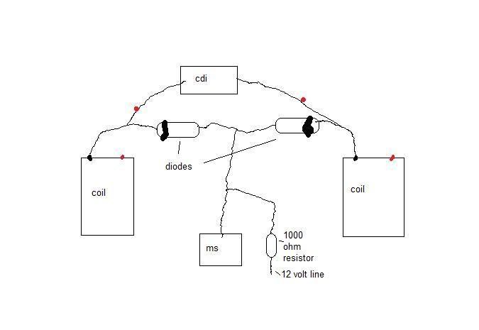
                          Possible solution for triggering

                          From the Katana site
                          1A. The new way of doing this is to trigger off the negative side of the coil. This was intentionally avoided for the initial construction due to the MS being susceptible to damage from CDI type coils. The katana ignitor, while called the CDI, is actually NOT a CDI type ingition. It uses standard coils which CAN be used by MS. The only change required is a pair of diodes preventing the ignitor from firing both coils at once and then adding a 12v pull up circuit with a 1000ohm resistor. This is the new diagram to use, all wires can be found at the igniter itself; there is no need to run wires all the way from each coil to the MS:


                          Note that the new ignition circuit still pipes into the MS on pin 24, same as the HEI diagram shows. Also pay attention to the orientation of the diodes, the banded end MUST match my diagram. Diodes are 1N4001 types, you'll have at least 2 spares in an MS2.2 kit for your use.

                          Comment


                            (cont.) possible trigger solution

                            This is the thinking behind the Kat site

                            The two diodes prevent power from flowing back into the coils, but it allows a signal out. The downfall of this is that it causes no voltage to flow into the MS. So you need to wire in a 12 volt "pull up" using a 1kohm resistor. This allows a tiny amout of current to bring the line up to 12 volts when a coil is not firing. When the coil fires, it quickly drains that line faster than the resistor can refill it. So the MS sees the signal go 12-0-12-0-12-0 etc, where with no pullup it would be nothing but zero volts ever. I might have been able to reverse the diodes so the line fills with power when the coil isnt firing, but depending on the rate of drain the MS has on the tach line it may not have worked. My diagram looks very spread out, but all of the wires you need are on the 6 pin plug on the CDI box. Power is orange-white, coil one is white, coil 2 is black-yellow. So to do this I didnt even add wires, just bridged a few by soldering diodes and resistors in.

                            And it worked! Bike now idles smoothly down to a previously unseen 800 RPM! Tach signal is smooth and accurate. Bike revs freely and comes down to rest at idle with no hiccups.

                            I still have NO idea why 2 cyl mode doesnt work. It worked for the turbo guy in the link above. It ran my bike too, but wouldnt idle right. I don't get it, but I'm not wasting anymore time worrying about it. It works now, in the correct 4 cyl mode. Now I need an oil temp sensor and this thing should be ready for DD duty.

                            EDIT: Wow that picture came up small. If anyone really needs to see it in full detail I'll resize it.

                            Also, if I understand the theory correctly, another gentleman used the similar triggering for an XS1100

                            Comment


                              Nice to see something happening here. I had wondered if this project was dead. Not wishing to gloat but I am up & running with my Katana & have been for a month now. I have ridden it & am now doing as much logging & mapping as I can. No issues so far but then I didn't really expect any as I have only learned & copied from other peoples projects. Just need to fit my tip over sensor & its all finished - for now anyway.
                              Nick

                              Comment


                                Originally posted by 2whldreams View Post
                                This is the thinking behind the Kat site

                                The two diodes prevent power from flowing back into the coils, but it allows a signal out. The downfall of this is that it causes no voltage to flow into the MS. So you need to wire in a 12 volt "pull up" using a 1kohm resistor. This allows a tiny amout of current to bring the line up to 12 volts when a coil is not firing. When the coil fires, it quickly drains that line faster than the resistor can refill it. So the MS sees the signal go 12-0-12-0-12-0 etc, where with no pullup it would be nothing but zero volts ever. I might have been able to reverse the diodes so the line fills with power when the coil isnt firing, but depending on the rate of drain the MS has on the tach line it may not have worked. My diagram looks very spread out, but all of the wires you need are on the 6 pin plug on the CDI box. Power is orange-white, coil one is white, coil 2 is black-yellow. So to do this I didnt even add wires, just bridged a few by soldering diodes and resistors in.

                                And it worked! Bike now idles smoothly down to a previously unseen 800 RPM! Tach signal is smooth and accurate. Bike revs freely and comes down to rest at idle with no hiccups.

                                I still have NO idea why 2 cyl mode doesnt work. It worked for the turbo guy in the link above. It ran my bike too, but wouldnt idle right. I don't get it, but I'm not wasting anymore time worrying about it. It works now, in the correct 4 cyl mode. Now I need an oil temp sensor and this thing should be ready for DD duty.

                                EDIT: Wow that picture came up small. If anyone really needs to see it in full detail I'll resize it.

                                Also, if I understand the theory correctly, another gentleman used the similar triggering for an XS1100
                                That was called the GSXR mod on the MSExtra site. I tried it via a plug-in harness and had no useable signal. To use it, I'd need to buy another ignitor box to use and of course this disallows any ignition control. I'm currently waiting for Arttu to have a trigger wheel setup made so I can try that.

                                The project is not dead, just on parts hold again. I'm glad the other one is up & running.

                                Comment

                                Working...
                                X