• Required reading for all forum users!!!

    Welcome!
    Register to access the full functionality of the GSResources forum. Until you register and activate your account you will not have full forum access, nor will you be able to post or reply to messages.

    A note to new registrants...
    All new forum registrations must be activated via email before you have full access to the forum.

    A Special Note about Email accounts!
    DO NOT SIGN UP USING hotmail, outlook, gmx, sbcglobal, att, bellsouth or email.com. They delete our forum signup emails.

    A note to old forum members...
    I receive numerous requests from people who can no longer log in because their accounts were deleted. As mentioned in the forum FAQ, user accounts are deleted if you haven't logged in for the past 6 months. If you can't log in, then create a new forum account. If you don't get an error message, then check your email account for an activation message. If you get a message stating that the email address is already in use, then your account still exists so follow the instructions in the forum FAQ for resetting your password.

    Have you forgotten your password or have a new email address? Then read the forum FAQ for details on how to reset it.

    Any email requests for "can't log in anymore" problems or "lost my password" problems will be deleted. Read the forum FAQ and follow the instructions there - that's what we have one for...

  • Returning Visitors

    If you are a returning visitor who never received your confirmation email, then odds are your email provider is blockinig emails from our server. The only thing that can be done to get around this is you will have to try creating another forum account using an email address from another domain.

    If you are a returning visitor to the forum and can't log in using your old forum name and password but used to be able to then chances are your account is deleted. Purges of the databases are done regularly. You will have to create a new forum account and you should be all set.

1150 Oh no! Off one tooth on cam timing? Pics too.

Carter Turk

Forum Sage
Charter Member
I was re torquing head bolts and followed up with checking the valve clearance. All were good except #3 exhaust were a tad tight.

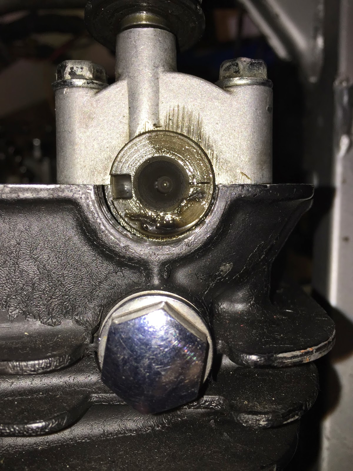
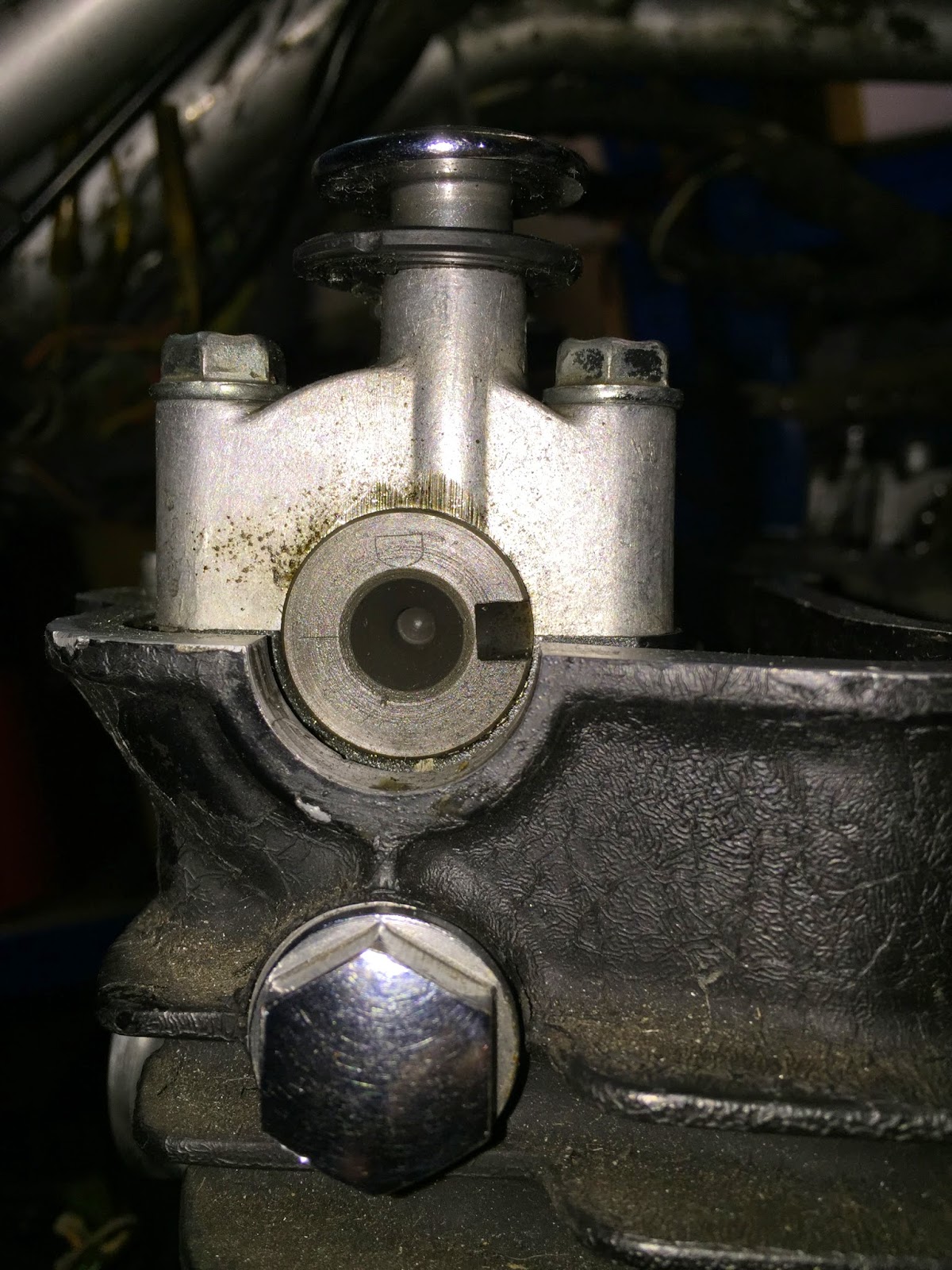
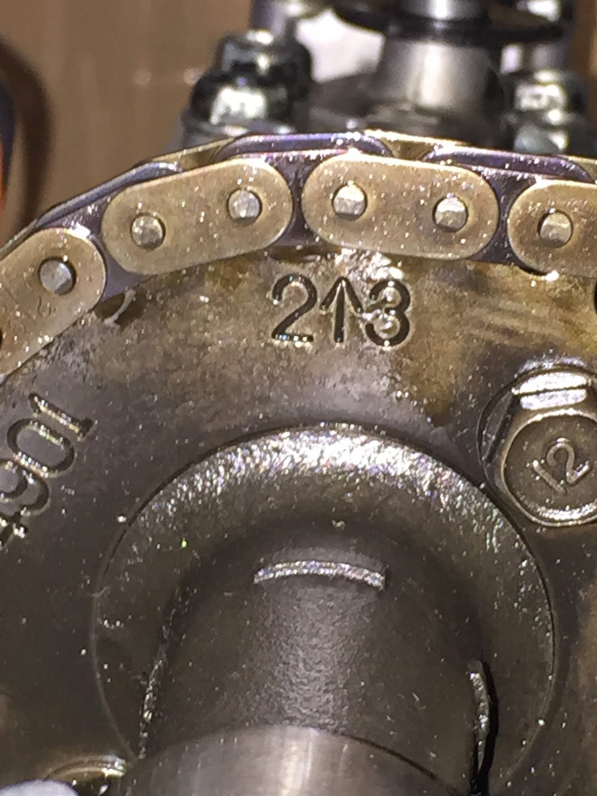
Then I noticed the arrows on the cam weren't exactly flush with head surface. Nor were the notches in the cams. On page 3-68 in the 1150 factory manual,

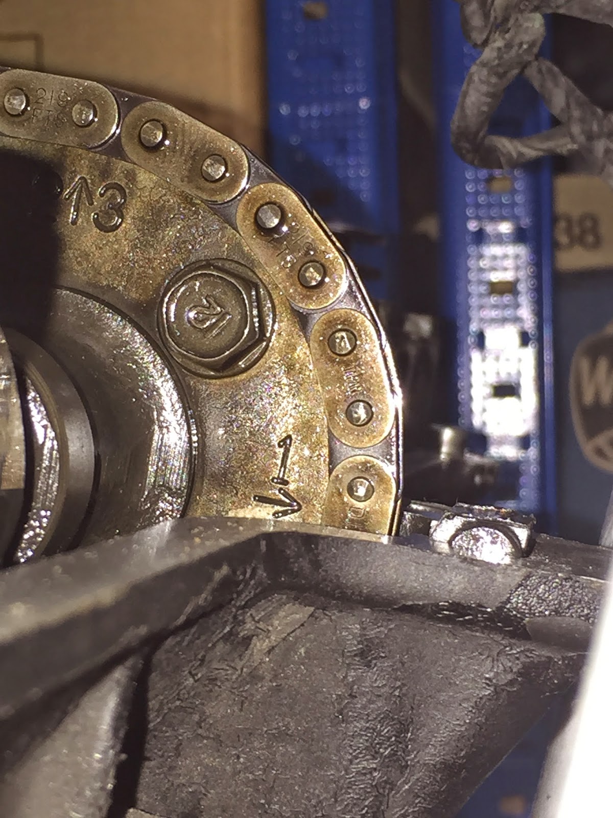
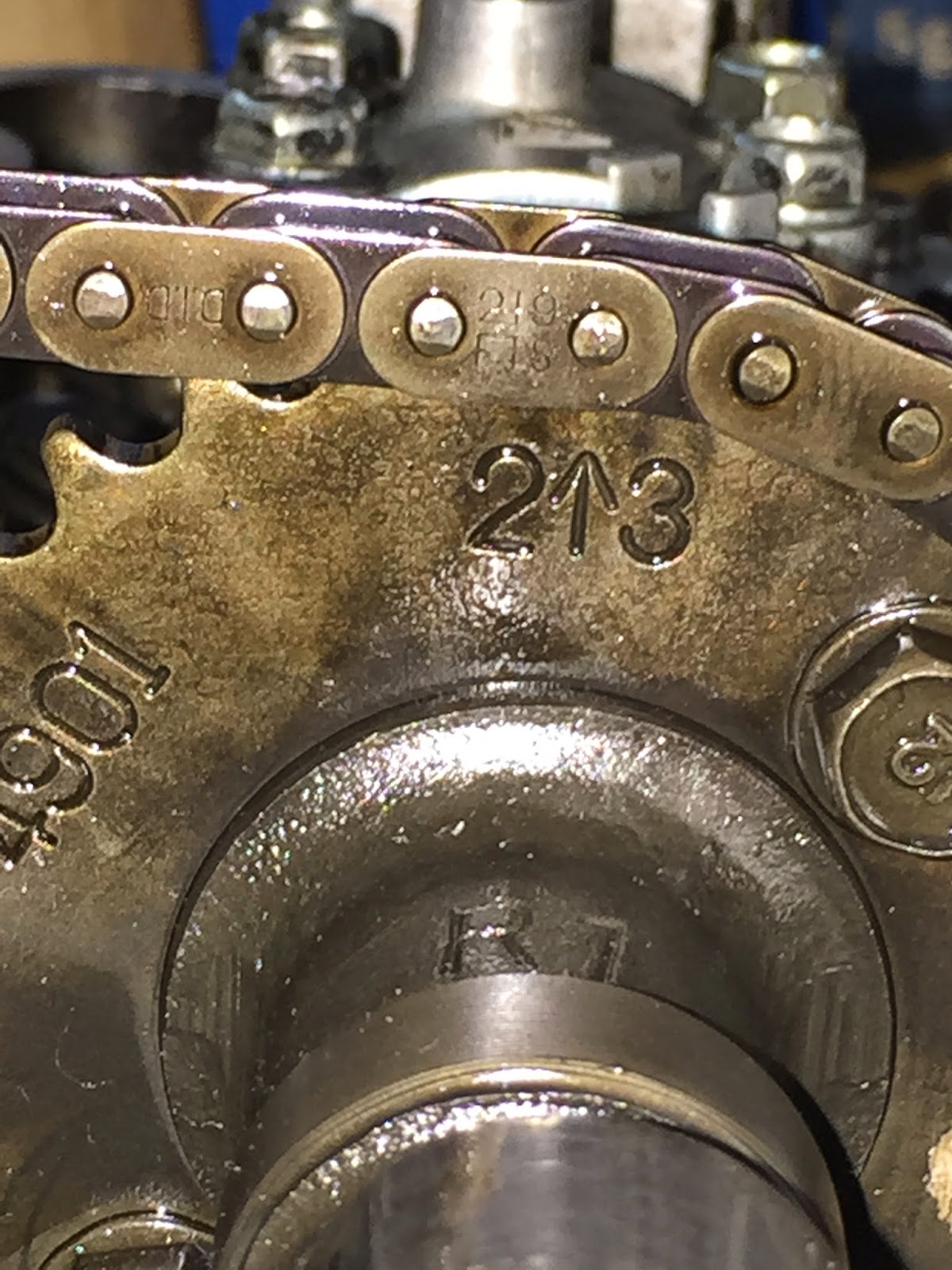
they show a "bubble" close up of the cam chain. It says something to the effect that the cam chain side plates must meet the head surface inbetween plates.

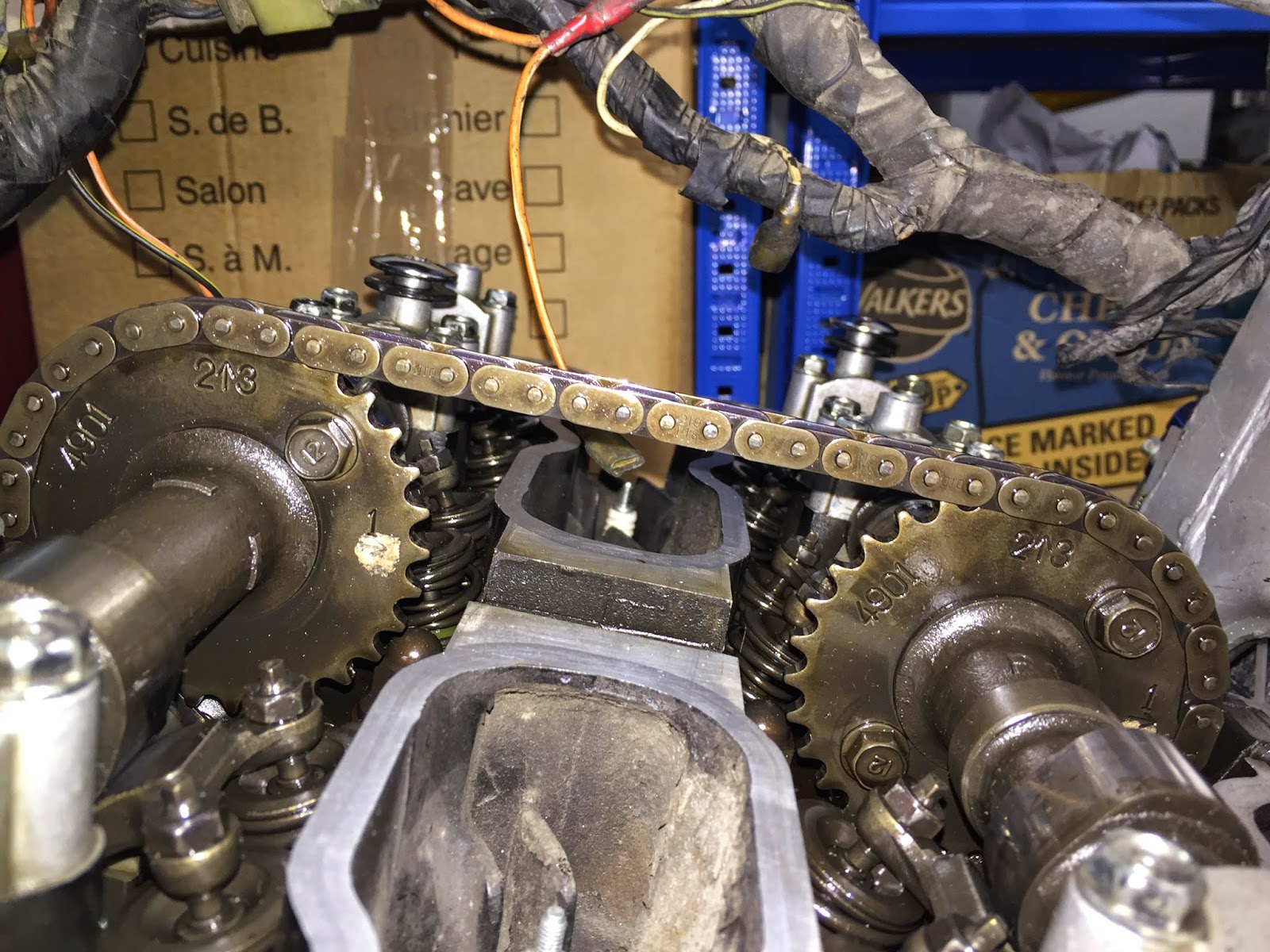
This is on the exhaust cam side. When my arrow lines up, it's pointing right through a cam chain plate. I'm 20 pins from arrow to arrow on top of the cams.

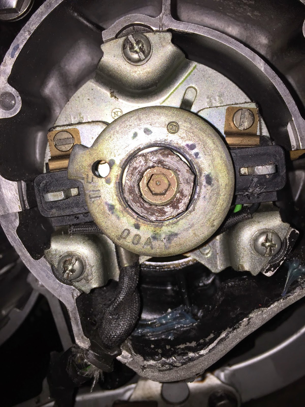
The T mark on the ignition does not line up with the fixed mark on the engine, when the notches are where they're supposed to be. I don't recall the positions

being this wonky 200 miles ago when I last adjusted the valves, but I guess I flaked out. In either position the valve clearance is the same. Any words of

Wisdom appreciated. Clearly, I've lost some of mine.

2nd picture show the arrows flush, but the T-mark is off on the ignition
 
The pin on the intake cam, is one pin forward of the picture shown on 3-68 in the manual. If I move the chain so it's pointing inbetween side plates, the starting pin won't be in the right spot either. Unless the picture is for illustration purposes only.
 
Carter, did you set the T mark on the timing plate before you set the cams? It sounds like you might be 1 pin off on both cams to me.

V
 
Exhaust #1 should point at the head surface and twenty pins between 2 on exhaust and 3 on intake.
Looks like one tooth off on the exhaust. If you change it and the #1 arrow points down from the head surface you had it right.
 
Measure the cam chain in case it's stretched. That would be a lot of stretch but if the intake 1 arrow lines up and you count 20 teeth (sorry I meant pins) the exhaust 1 arrow should line up. That measurement has no relation to any other timing marks.
If the chain is a 1/2 pitch chain your measurement from #2 to #3 should be 19 (links) x .5 = 9.5". I'm just guessing on the pitch but just substitute the correct pitch of not right.
 
Last edited:
This is a brand new cam chain, with 200 miles on it. I'm using a mechanical advancer from the 83 Kat with a Dyna-S.
Do you guys think the illustration is valid? If I move the chain, the pins won't line up as shown. Also, the timing mark is in a different location (9:00 on 1150 advancer, and more like 12:00 on the mechanical one. Not sure if that's relevant, since it's "keyed" into the end of the crank.
 
Ok, here's another thought. In my '84 750 manual it shows the distance of 20 pins also and using the mark #1 on the exhaust cam lining up with the cylinder head gasket surface. However they show 2 different cam sprockets. Exhaust cam sprocket marked #2 and intake marked #3. The exhaust sprocket has the #1 reference for cam position and #3 sprocket has no reference for cam position, you just count the 20 pins and be done with it. Because your sprockets are both the same I wonder if you're supposed to just ignore the cam position mark #1 on the intake cam. You have no control or adjustment between the cam sprockets, only the distance of the 20 pins. The mark on the crank times the cams to the crank, your 20 pin count times the cams to each other. In other words the cams appear to be timed correctly.

CamTiming_zps716mk4y1.jpg
 
Last edited:
Ok, here's another thought. In my '84 750 manual it shows the distance of 20 pins also and using the mark #1 on the exhaust cam lining up with the cylinder head gasket surface. However they show 2 different cam sprockets. Exhaust cam sprocket marked #2 and intake marked #3. The exhaust sprocket has the #1 reference for cam position and #3 sprocket has no reference for cam position, you just count the 20 pins and be done with it. Because your sprockets are both the same I wonder if you're supposed to just ignore the cam position mark #1 on the intake cam. You have no control or adjustment between the cam sprockets, only the distance of the 20 pins. The mark on the
crank times the cams to the crank, your 20 pin count times the cams to each other. In other words the cams appear to
be timed correctly.

Thanks for the nice diagram. It's the notches on the end of the cam that aren't in the proper position, when the timing mark aligns. They are not facing exactly inwards or outwards. I think you could double check the intake cam without the #1 mark, by the notches facing in or out. Not looking forward to pulling all the caps.
 
Carter, keep in mind that the cams move at HALF the speed of the crank. If you pull the cams & rotate the crank 360 degrees, the chain links come up 1 pin different for alignment purposes. In other words, one way the front pin on a link is correct, 360 from that the rear pin on the link is correct. Do you follow?
Ray.
 
Sort of, but will the #1 arrow on the exhaust cam point in-between the side plates? So I need to rotate 360 with cams out to change the position of the links?
 
One thing you might consider while you are doing this, is upgrade to the slotted cam sprockets. You can fine tune your cams for the best performance at some time.
 
not saying anything bad but.......
degreeing cams are MUCH more difficult than installing stock cams and sprockets.
i agree people should buy the tools and learn to do it but just to go at it blind...
i see a bent valve thread if that's the case..:pray:
 
I misinterpreted your problem thinking it was a problem with where the arrow was on the intake cam, sorry about that. If the exhaust marks aren't lining up then you most likely have to retime them. lf you have to maybe by removing the chain tensioner and maybe one sprocket you'll have enough wiggle room to move things around. Good luck with it.
 
The notches are off, inward or outward when on the fixed timing mark. Don't know how I did that with the factory manual sitting right next to me. I'll pull them and report back. I did find an older picture I had showing the exhaust cam #1 arrow pointing flush with the case, but the arrow was pointing straight through a side plate.
 
One tooth off on each sprocket. The arrow even points between plates like they show on 3-68.

One weird discrepancy is the illustration in the manual shows 5 side plates between #1 on the exhaust cam and #2, when there's only 4 side plates. Haven't fired it up yet.
 
Bit behind the times on this one but I just did it myself and had some fun.

One thing I found is that if you pull up the front cam chain guide, it allows enough slack (with the cam chain tensioner removed) to allow you to slip the chain off the cam chain sprocket and move it along a link or two.

My problem was that I got it all lined up at the top but the T mark was way off on the crankshaft end.

All of these need to line up:

IMG_5695.JPG


IMG_5696.JPG


IMG_5697.JPG


IMG_5699.JPG


IMG_5701.JPG


IMG_5702.JPG


IMG_5703.JPG


And I finally managed to get 20 pins between the 2/3 markers. I never ended up with the no.1 arrow pointing to a gap between 2 chain links. My no. 1 points to the middle of a chain link. I'm guessing that the line drawing in the post above is not entirely accurate, as it would be impossible to have the no. 1 pointing between 2 links and the exhaust cam 2/3 mark pointing at a chain pin.

Or have I cocked it up somewhere a long the line?

Greetings
 
Back
Top