• Required reading for all forum users!!!

    Welcome!
    Register to access the full functionality of the GSResources forum. Until you register and activate your account you will not have full forum access, nor will you be able to post or reply to messages.

    A note to new registrants...
    All new forum registrations must be activated via email before you have full access to the forum.

    A Special Note about Email accounts!
    DO NOT SIGN UP USING hotmail, outlook, gmx, sbcglobal, att, bellsouth or email.com. They delete our forum signup emails.

    A note to old forum members...
    I receive numerous requests from people who can no longer log in because their accounts were deleted. As mentioned in the forum FAQ, user accounts are deleted if you haven't logged in for the past 6 months. If you can't log in, then create a new forum account. If you don't get an error message, then check your email account for an activation message. If you get a message stating that the email address is already in use, then your account still exists so follow the instructions in the forum FAQ for resetting your password.

    Have you forgotten your password or have a new email address? Then read the forum FAQ for details on how to reset it.

    Any email requests for "can't log in anymore" problems or "lost my password" problems will be deleted. Read the forum FAQ and follow the instructions there - that's what we have one for...

  • Returning Visitors

    If you are a returning visitor who never received your confirmation email, then odds are your email provider is blockinig emails from our server. The only thing that can be done to get around this is you will have to try creating another forum account using an email address from another domain.

    If you are a returning visitor to the forum and can't log in using your old forum name and password but used to be able to then chances are your account is deleted. Purges of the databases are done regularly. You will have to create a new forum account and you should be all set.

1977 GS400 help with mystery of the right ignition points

  • Thread starter Thread starter Guest
  • Start date Start date
G

Guest

Guest
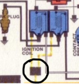
After trying to statically time my bike, I have been unable to get the right contact points to light up with my continuity tester. I have jiggled the subplate in every way possible, replaced points, replaced the right condenser (I am replacing the left one, but I had to order another one seperately) but still no signal. I was thinking of replacing the coil wires, does anyone know where I should get these? I am very confused by this problem to be honest, because I was getting spark on my right cylinder while running it and riding around. I did notice that the exhaust was a bit sootier than the left one so I am guessing it does have a weaker spark. What else should I try testing/replaciing in order to try and fix this? I was thinking of replacing HT leads, plug caps, but I am not actually sure if these could cause this.
 
Last edited:
Did you make sure the points are riding on the insulating spacers? Take them off, and see if you have continuity. The condensers are capacitors, their to keep the points from burning up. It has nothing to do with continuity, unless the components are grounding out. A picture is worth a 1000 words. I'd have to be holding the coil in my hand to see, but those coil wires are usually glued into the coils, and will come out. You can get automotive bulk coil wire to make the lengths you need, you just push the wire so that it goes onto the pin in the hole and crimp on ends for the spark plugs. ;)
 
Hi, thank you for the advice. Do you mean to take off the insulating spacers and test then? And I think you're right that the wires are just glued on. I will try replacing the wires on both sides to see if that helps.
 
Okay, please note that this is coming from an old Ford Flathead guru. Looks to me like the right hand set of points is open. If a GS400 is a twin cylinder? And a parallel twin at that?, and both pistons go up and down together, then that ignition system may use TWO sets of points to make the ignition fire ONCE. Does it have only one coil?

The hot ticket back in my flatly days was to run dual points, one set of points would “make” (turn the coil on) and the other set of points would “break” (turn the coil off) causing the coil to discharge. This would allow us to pick up a few degrees of coil dwell by overlapping the opening and closing action of dual points.

What say ye?
 
Okay, forget what I wrote above. I found a GS400 wiring diagram and I see that the GS400 has dual coils.
The GS400 feeds the ignition coils roughly battery voltage and the ignition points provide ground side control of coils.
What that means is most of the voltage is dropped across the coils (that’s a good thing), so the points only see a few volts as they make and break the coil circuits (also a good thing- minimizes point arching).

With the ignition system on, put your volt meter positive probe on the white wire feeding the left set of points and the negative probe to a good ground and read the voltage. If the points are open, you should see near battery voltage, and if the points are closed you should see single digit voltage.

Now do the same with the black wire feeding the right set of points. If you are not getting any voltage at the black wire you will need to grab a wiring diagram and work back words to see at what point the black wire has voltage. You could have an internal open in the right hand coil’s primary winding and that would cause the black wire to be dead. Or perhaps the right hand coil is not even receiving any voltage. (Sounds like a treasure hunt, eh?)

Or perhaps you could remove the coils and swap sides and then redo your voltage readings to see what effect that has on your voltage readings.

Let is know what you find.
 
Last edited:
Hey, thank you for the detailed advice, haven't had time to get to this but when I will I will let you know the results!
 
Okay, forget what I wrote above. I found a GS400 wiring diagram and I see that the GS400 has dual coils.
The GS400 feeds the ignition coils roughly battery voltage and the ignition points provide ground side control of coils.
What that means is most of the voltage is dropped across the coils (that’s a good thing), so the points only see a few volts as they make and break the coil circuits (also a good thing- minimizes point arching).

With the ignition system on, put your volt meter positive probe on the white wire feeding the left set of points and the negative probe to a good ground and read the voltage. If the points are open, you should see near battery voltage, and if the points are closed you should see single digit voltage.

Now do the same with the black wire feeding the right set of points. If you are not getting any voltage at the black wire you will need to grab a wiring diagram and work back words to see at what point the black wire has voltage. You could have an internal open in the right hand coil’s primary winding and that would cause the black wire to be dead. Or perhaps the right hand coil is not even receiving any voltage. (Sounds like a treasure hunt, eh?)

Or perhaps you could remove the coils and swap sides and then redo your voltage readings to see what effect that has on your voltage readings.

Let is know what you find.

Coming back 5 months later! Hope its not against server ettiquette, I just didn't wanna make a new post and clog stuff up. I think I figured out what the problem is. I decided to disconnect the coils from the points, and see if the test light worked then, and boom, everything worked like it should. I then connected the black connector and the white one, and tested, and it still worked normally. But when I connected each of the orange wires coming from each coil into the wire connector thing, when testing contiuity with my (battery powered) test light, the light would remain on even when the contact points were not touching. This was done with the ignition off and battery disconected. I am guessing this means that this orange wire is somewhere grounding somewhere down the line, how should I go about finding where this is? Thank you for your help!
 
Coming back 5 months later! Hope its not against server ettiquette, I just didn't wanna make a new post and clog stuff up. I think I figured out what the problem is. I decided to disconnect the coils from the points, and see if the test light worked then, and boom, everything worked like it should. I then connected the black connector and the white one, and tested, and it still worked normally. But when I connected each of the orange wires coming from each coil into the wire connector thing, when testing contiuity with my (battery powered) test light, the light would remain on even when the contact points were not touching. This was done with the ignition off and battery disconected. I am guessing this means that this orange wire is somewhere grounding somewhere down the line, how should I go about finding where this is? Thank you for your help!

I am having a problem following just where your probes are being connected and what type of test light you are using. And “everything worked as it should” doesn’t seem to tell me much.

But if you disconnected the orange wires from their respective coils and connected a meter probe to each orange wire, the meter should show continuity between those two orange wires as they are connected together in the wiring harness. See the wiring diagram in an earlier post.

I’ll have to go back and reread the issues you are having and respond later.
 
Sorry to be unclear, I meant that everything worked as it should in the points when the orange/white wire was disconnected, eg continuity broke when the points were separated instead of the test light (battery powered one) being on all the time even when the points separated. When I connect the orange/white wires from each coil to the dual connector in the harness, there seems to be a short down the line from there, that is the problem I have now. When the orange/white wires are the in the connector (circled below in the attached image), my test light is constantly lit, even when I rotate the engine and the points break. (The probe is on one of the point connectors and a ground). I am going to clean the connector with vinegar/salt and see if that helps the problem. I also did test the primary windings with a multimeter and got 5 ohms which indicates that the coil is not at fault right? Thank you again for everyone's help, even when I am being vague/unclear, I am not very skilled at mechanics in general, and electrical stuff even less so. Without this forum, I would be even more lost than I am :)

EDIT: i should also add that before I was only having the problem with the test light showing continuity all the time even when the points broke just on the right points, but now the left also shows that problem when the orange/white wire of the left coil are connected in the harness as well.
 

Attachments

  • coil.png
    coil.png
    27.6 KB · Views: 0
Last edited:
With the ignition on I put the red probe onto the connector where the two orange/white wires from the coils meet (circled above) and the black probe on a ground and I got 12.5 volts. Does this indicate that the coils are receiving battery voltage? I also noticed that the orange/white wire seem to have a ground on the coil, could these grounds going bad cause the system to short?
 
With the ignition turned on, (I assume all other connections to the coils and points are back to original), your meter is reading battery voltage *IF* both points are open, or it is reading voltage available (that would be battery voltage minus voltage drop) to the ignition coils if either point is closed. (Note: there is no voltage drop if current is not flowing.)

How are you noticing that the orange/white wire “seems to have a ground on the coil”?
I don’t understand?
 
In the photo I attached, i mean where the orange and white wire is attached to the coil under a layer of like waxy stuff. Or is that not a ground and just where it attaches?
 
Orange/white wire should not be going to a ground. Orange/white wire is the “hot” wire going to the coil to power up the coils. In the picture you attached those wires look like black wires to me that maybe have a metal clamp to hold them in position so they don’t end up someplace they shouldn’t be. The black wire and the white wire connect the ground side of their respective coil to the ignition points. The points are on the ground side of the coils, grounding the coil circuit when it is time to flow current through the coil primary side. When the points open to stop the flow of current through the coil primary side, it causes a high voltage to be induced into the secondary windings of the coil and causing a high voltage spark to flow down the spark plug wire to the sparky plug.

I am not familiar with this waxy stuff of which you speak. There should be a + side connector on the coil where power goes into the coil and a - side connector where power flows to the ignition points..
 
I think the waxy stuff is just what they used to cover the joint of the wire? It was on the joint where my condenser was wired to as well. Do you have any ideas what could be causing the condition where the points appear as always open except when I disconnect the "hot" wires of the coils? I am confused because the bike does run (poorly) which I don't understand how that would be possible if the points system was just not working ie not breaking the circuit when the points seperate.
 
I can only offer my SWAG (that’s my Silly Wild A@@ Guess) as to what might cause a set of points to always appear as open. Perhaps one of those condensers is internally shorted so as it doesn’t pass any (very much) current to its points and sucks the current to ground. That way the points never get a chance to “break” the coil primary circuit and cause a spark to be induced.

Maybe disconnect the condensers from the coils and put one meter probe to the coil side connection of the condenser and the other meter probe to a ground and see if one condenser has a short to ground. If one does short to ground then very little current would get to that point and it would appear as open. What do you think?
 
I can try that, but the condenser connection is soldered onto the coil, should I just remove that solder? I did also just replace the right condenser after discovering this issue and it didn't help anything. Another question, is it possible if the joint where the orange/white wire is connected is bad it could cause that permanently open effect?
 
Well, if the condenser is soldered to the coil, remove the orange/white wires from the coils so your meter can’t find a ground back out of the coil and then do as above to see if the meter finds ground through the condenser.
 
The orange wire are soldered as well, but it is probably time to inspect that joint to see if it's all buggered up as well
 
Or unplug the 2 orange/white wires from the wiring harness connector.

BTW, I see this gs400 is a vertical twin, so, since it has dual points, I suspect it is what I call an odd fire engine. In other words, the piston do not go up and down together, but actually one piston is going up when the other piston is going down. Is that correct?
 
Back
Top