• Required reading for all forum users!!!

    Welcome!
    Register to access the full functionality of the GSResources forum. Until you register and activate your account you will not have full forum access, nor will you be able to post or reply to messages.

    A note to new registrants...
    All new forum registrations must be activated via email before you have full access to the forum.

    A Special Note about Email accounts!
    DO NOT SIGN UP USING hotmail, outlook, gmx, sbcglobal, att, bellsouth or email.com. They delete our forum signup emails.

    A note to old forum members...
    I receive numerous requests from people who can no longer log in because their accounts were deleted. As mentioned in the forum FAQ, user accounts are deleted if you haven't logged in for the past 6 months. If you can't log in, then create a new forum account. If you don't get an error message, then check your email account for an activation message. If you get a message stating that the email address is already in use, then your account still exists so follow the instructions in the forum FAQ for resetting your password.

    Have you forgotten your password or have a new email address? Then read the forum FAQ for details on how to reset it.

    Any email requests for "can't log in anymore" problems or "lost my password" problems will be deleted. Read the forum FAQ and follow the instructions there - that's what we have one for...

  • Returning Visitors

    If you are a returning visitor who never received your confirmation email, then odds are your email provider is blockinig emails from our server. The only thing that can be done to get around this is you will have to try creating another forum account using an email address from another domain.

    If you are a returning visitor to the forum and can't log in using your old forum name and password but used to be able to then chances are your account is deleted. Purges of the databases are done regularly. You will have to create a new forum account and you should be all set.

24V start advice

  • Thread starter Thread starter Guest
  • Start date Start date
G

Guest

Guest
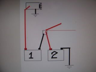
I am building a 1395cc self starting bike and need to be able to run 24V to the starter. That in itself is the easy part. The hard part is that i want to be able to charge the second battery off the stock charging system. In order to do so i seed to do series/parallel switching.

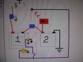
I want to know if this schematic will produce the results that I expect. Clutch switch will be used to engage series operation. The relays won't have to switch under load.

seriesparallel.jpg


I Think these relays would do the job:

http://www.pickercomponents.com/Data_Sheets/PC7150_Data_Sheet.pdf

There is this product for the hayabusa that i got the inspiration from"

http://www.schnitzracingstore.com/catalogs/catalog.asp?prodid=5145756&showprevnext=1#


Any advice would be appreciated,

Sean
 
First: I am not familiar with the terminal number designations to know which is the coil, which is the commom, which is the N.O., which is the N.C.
I suppose I could find that info (or maybe I should know it anyway, seeing how that I work with industrial controls). But at the moment cant really evaluate your circuitry.

Second: Why use the clutch switch as the trigger to the relays? Seems like then it would be switching every time you shifted.
I understand that you want the relays to switch the batterys from parrallel (12 volt, most of the time) to series (24volt for when running the starter motor). Why not trigger the relays with the starter button? Maybe you are thinking to make the switch from 12 to 24 volt before making the starter solenoid pull in, but seems to me that could do both at same time.

THird: Relay contacts need to be rated for the amp load of the starter.
 
Last edited:
Ah, now see:
85 is coil -
86 is coil +
30 is contact common
87 is contact N.O.
87A is contact N.C.

And contacts rated at 100amp breaking and 150 amp continous, so should be good there.

Your wiring to 85 and 86 seems strange.
Seems like would want both 85s to negitive (or ground) and both the 86s to the starter button (or whatever you use as the trigger to swtich from parrellel to series).
And do not need any connection of "ignition 12vdc".

You schematic does not show the charging system, but we know that is connected in on the main battery+ and the main solenoid.

I have not really looked at your series/parrellel wiring on the relay contacts (and need to get back to work).
But need to do it such that when the batterys are in series (24 volts) that the 24volts is connected to the starter/solenoid only, and the rest of the bike wiring is still only on the main battery (12v).

.

.
 
Last edited:
By using the clutch switch to activate I don't have to worry as much about the contacts welding inside the relay when i hit the start button. Also acts as a starter safety interlock
 
Interested in some background as to the intended purpose for the self starting? The 24 volt start will usually crank the engine a bit faster and reduce starter wear unless it is greatly overloaded.

The hook-up is a simple series/parrallel problem which seems to be addressed by your circuit. I do share Redman's concern regarding the use of the clutch switch as this would seem to cycle the relays when shifting.

You may also wish to consider the possible effects of induction created voltage spikes from the relay coils into the bike's electrical system. I would put an oscilloscope across the winding circuit before putting the circuit into service. A damper capacitor or damper resistor across each relay trigger winding may be useful in order to protect electronics.

HIH

Norm
 
You can do it much easier than your diagram. Mine works like a champ.

I have a drawing of how it's done, I'll have to get it up here for you.
 
Interested in some background as to the intended purpose for the self starting? The 24 volt start will usually crank the engine a bit faster and reduce starter wear unless it is greatly overloaded.

The hook-up is a simple series/parrallel problem which seems to be addressed by your circuit. I do share Redman's concern regarding the use of the clutch switch as this would seem to cycle the relays when shifting.

You may also wish to consider the possible effects of induction created voltage spikes from the relay coils into the bike's electrical system. I would put an oscilloscope across the winding circuit before putting the circuit into service. A damper capacitor or damper resistor across each relay trigger winding may be useful in order to protect electronics.

HIH

Norm

I can easily add a suppression diode across pins 85 and 86 of each relay. Using the clutch switch to activate the relays is the way the commercially available ones for the hayabusa work. It would be asking alot of those relays to switch while the starter is engaging. I guess I could rig up a momentary push button or switch to activate for starting.

I had the starter rebuild by Paul Cashio for use on 24V to handle starting a big bore high compression engine.

I know I could do this easily with just a switch instead of the relays, but I like the idea of it switching automatically so i don't end up with a low battery because I forgot to switch it to charge.
 
Last edited:
DSC00810.jpg


#1 is the starting battery The(+) is connected to the starter motor - and solenoid only. it makes 24 volt hit the starter when the solenoid is activated. I use a YB10LA2

#2 is the main operating battery (+12V) connected to the positive side of the starter solenoid and (-)to frame ground. ALL 12V systems come off the (+) terminal or solenoid nut. You can use all the relays/ starter interlock systems you like. I use a AGM 18~20 ah/hr battery.

I show the other red connections genericly . They go to the main fuse block / key switch~ and all 12V circuits. They are protected by the starter load because it uses it all up the extra volts when in action.

it works/charges my bike like this.
 
Last edited:
DSC00810.jpg


#1 is the starting battery + connected to the starter motor - it makes 24 volt hit the starter when the solenoid is activated. I use a YB10LA2

#2 is the main operating battery (+12V) connected to the starter solenoid and all 12V systems come off the (+) terminal or solenoid nut I use a AGM 18~20 ah/hr battery.

I show the other red connections genericly . They go to the main fuse block and all 12V circuits. They are protected by the starter load when using the starter. it works/charges my bike like this.

This doesn't let the starting battery get charged by the stock charging system, does it?
 
I'm sorry I did not include that detail. I get so many starts out of mine I just use my home charger for battery #1. (6~10 starts) maybe more


I deleted the last drawing it is wrong... excellent challenge .. I need a little time to try different configurations with 2 starter solenoids and 2 relays.
 
Last edited:
Not sure if it would fit on your bike, but some older trucks (mid-70s Freighliners, Kenworths, etc.) had 12/24 systems.

Might be worth a look to see how they did it, as it would certainly handle the load for your bike. :D

.
 
Not sure if it would fit on your bike, but some older trucks (mid-70s Freighliners, Kenworths, etc.) had 12/24 systems.

Might be worth a look to see how they did it, as it would certainly handle the load for your bike. :D

.

looked at them...heavy and expensive and overkill.
 
.............
.............
............. and the rest of the bike wiring is still only on the main battery (12v).


.

TripPivots idea is great.
- The extra battery is esentailly after the soloenoid, and then not connected to the rest of the bike wiring.
- so have a series circuit of main battery then solenoid then extra battery then the starter.
- so extra battery is in series with the starter only,
- and the original batterys wiring is unchanged.
- does not use any relays.

But, yah, TripPivots idea does not address the recharging of the extra battery.

I would say to to use TripPivots general idea, but then can aslo use the relays to switch the extra battery out of the starter circuit and into the charging circuit.

Present stock wiring of starter solenoid coil is:
fuse to kill switch
kill swtich to starter button (and ignition module)
starter button to clutch switch (called interlock on suzuki schematic)
clutch switch to solenoid+
(and case of solenoid grounded thru its mounting and a black/white wire from harness).

I see, you are thinking that clutch switch can activate the relays first, then starter button pull in the solenoid.

If you have the batterys like TripPivot is suggesting, and then if you also have the relays switch the extra battery from the starter circuit to the charging circuit .... then better make sure that the relays switch before hit the starter button or will end up with the main battery positive connected to the negitive of the charging system (I assume I do not have to explain that would be bad). So might want to rewire the starter button and clutch switch the other way so:
Fuse to kill switch
Kill switch to clutch switch (and ignition)
Clutch switch to starter button and to the relay coils.
Starter button to solenoid.
 
The bike is going to have full custom wiring. Dyna 2000, vaypor digi dash, motogadget m-unit, keyless ignition. With my Schematic if you were to hit the start button with out the relays activated nothing would happen. I guess it would help if I add the starter button supplying 12V to the top of the starter relay.

seriesparallelrevised.jpg
 
That last picture looks pretty good, but you might want to consider either a fuse or a circuit breaker in the thin blue line between the main battery and the second solenoid.

Make it big enough to allow the secondary battery to charge, but small enough to protect the bike in case there is a problem at the relay (it's 15 amps in the stock bike).

Is this for a racing-only bike or a daily driver? The only concern is how many times the relays are going to get triggered by pulling the clutch.

.
 
It is going to be street and strip. There will be several fuses added where necessary, just didn't want to clutter up the drawing.
 
2 solenoids and 2 relays

2 solenoids and 2 relays

DSC00812.jpg


I have the parts to do this but I have not tested this drawing.

please forgive me for not doing a professional drawing.

I believe the solenoid between batt#1 and starter has to be a 2 wire starter button type to prevent 24 volts from melting the low amperage side of solenoid. I know the high amperage side of any solenoid can handle 24V. This is the only detail I have a question about. a single wire (like stock suzuki)may fail on the first attempt to use the starter. I know a single wire solenoid works between the batteries in a single starter solenoid configuration.

BLUE boxes are starter solenoids
GREEN circle is starter button
YELLOW boxes are relays ( 800 ohm bosch 5 prong - good ones) wire them normally closed-so they open when energized
RED box is just to show main 12V power
PURPLE line is momentary 12+V to open the relays and close the solenoids (start the bike). the relays close and the starter motor is isolated so battery #1 can now charge just like batt#2 .

please look this over and let me know what you think.
 
Last edited:
Back
Top