• Required reading for all forum users!!!

    Welcome!
    Register to access the full functionality of the GSResources forum. Until you register and activate your account you will not have full forum access, nor will you be able to post or reply to messages.

    A note to new registrants...
    All new forum registrations must be activated via email before you have full access to the forum.

    A Special Note about Email accounts!
    DO NOT SIGN UP USING hotmail, outlook, gmx, sbcglobal, att, bellsouth or email.com. They delete our forum signup emails.

    A note to old forum members...
    I receive numerous requests from people who can no longer log in because their accounts were deleted. As mentioned in the forum FAQ, user accounts are deleted if you haven't logged in for the past 6 months. If you can't log in, then create a new forum account. If you don't get an error message, then check your email account for an activation message. If you get a message stating that the email address is already in use, then your account still exists so follow the instructions in the forum FAQ for resetting your password.

    Have you forgotten your password or have a new email address? Then read the forum FAQ for details on how to reset it.

    Any email requests for "can't log in anymore" problems or "lost my password" problems will be deleted. Read the forum FAQ and follow the instructions there - that's what we have one for...

  • Returning Visitors

    If you are a returning visitor who never received your confirmation email, then odds are your email provider is blockinig emails from our server. The only thing that can be done to get around this is you will have to try creating another forum account using an email address from another domain.

    If you are a returning visitor to the forum and can't log in using your old forum name and password but used to be able to then chances are your account is deleted. Purges of the databases are done regularly. You will have to create a new forum account and you should be all set.

750 Katana Resurrection

KiwiAlfa156

Forum Mentor
Hi All,

I'm in the middle of bringing a 1982 Suzuki GS750S Katana back from the dead. I have been posting/blogging on the Katana Australia forum (Hi PeteGSX) but thought I might share the journey here too. It may be of interest to some of you. I'll gladly take any advice or comments, and am happy to answer questions. I've done a few restorations for road use, not show bikes. "Ride it, don't hide it", they say.

With every project, I've tried to do more and more of the work myself to a level I can be proud of. Last build (my daily rider GS650G Katana) it was all the paint and panel work.

TXdrZvRdGKwzBOzgtXl82_JORovktQPtmxSWQcryuzst2yG3THrl7G0frS9IurguHYsbSZcFrZb4l5-k82QeUkNPrwsKmKVE41I1KWFPzqrMz0bH63U66UrLyx2csavWK0QtTFw-Ug=s0


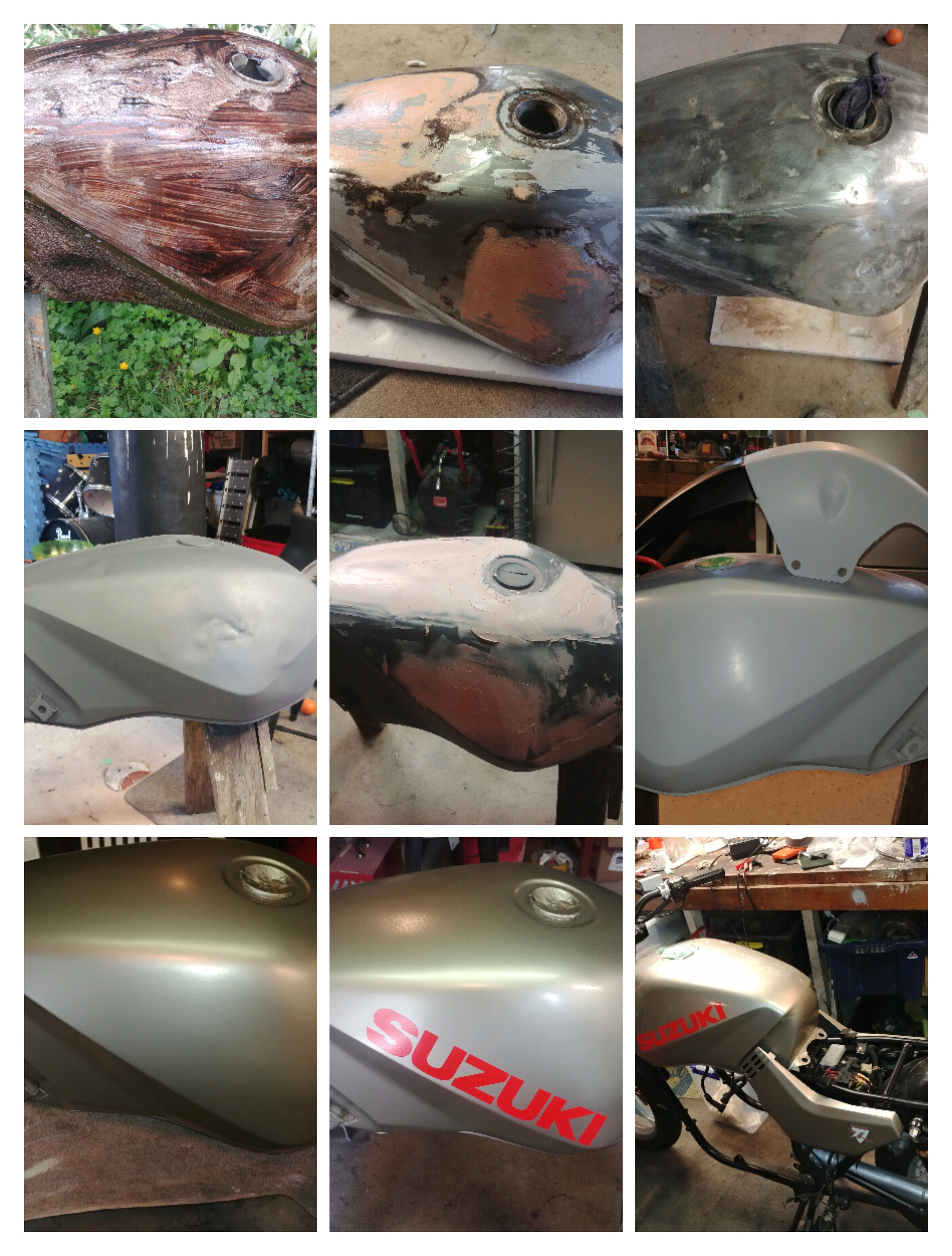
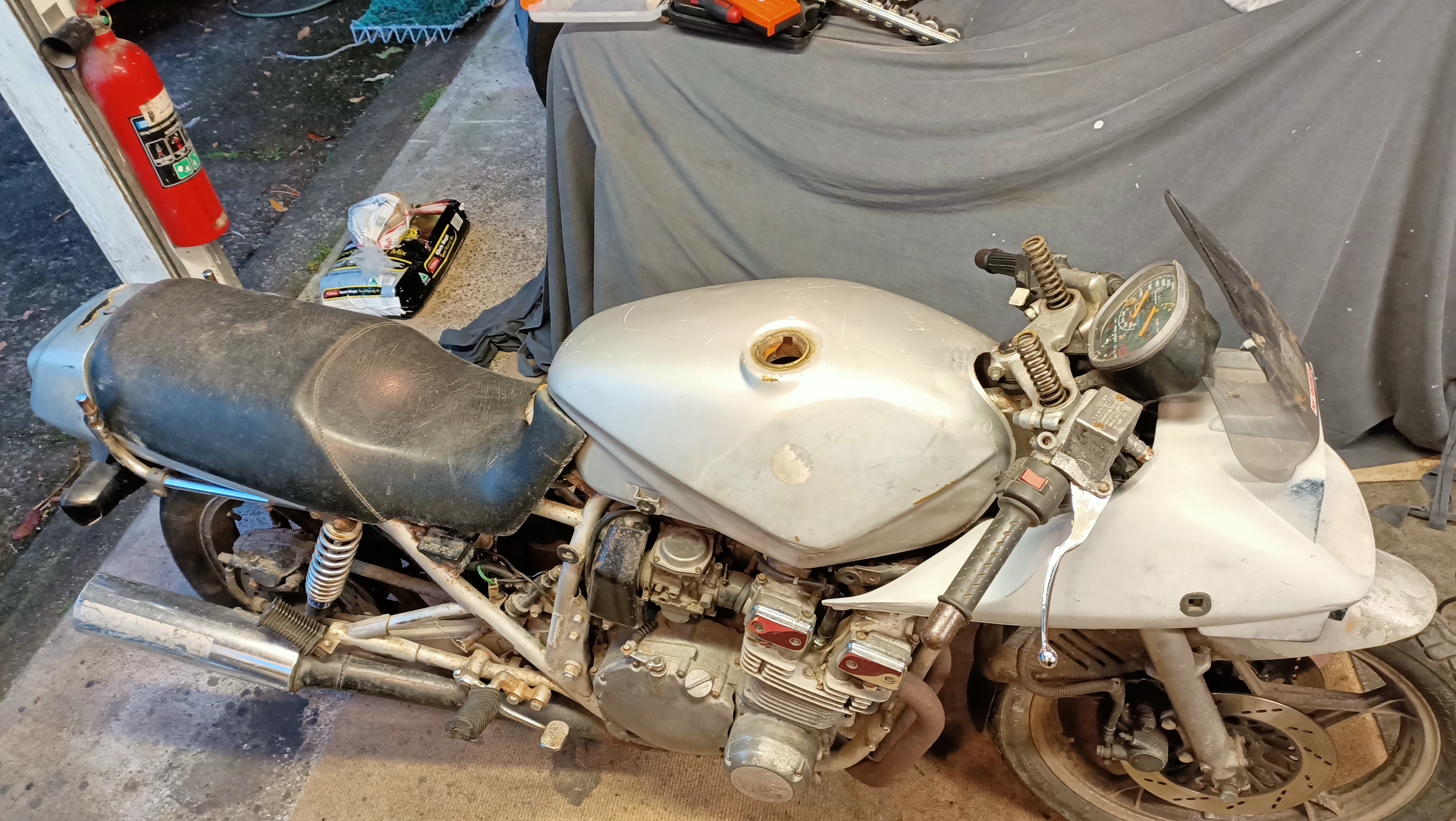
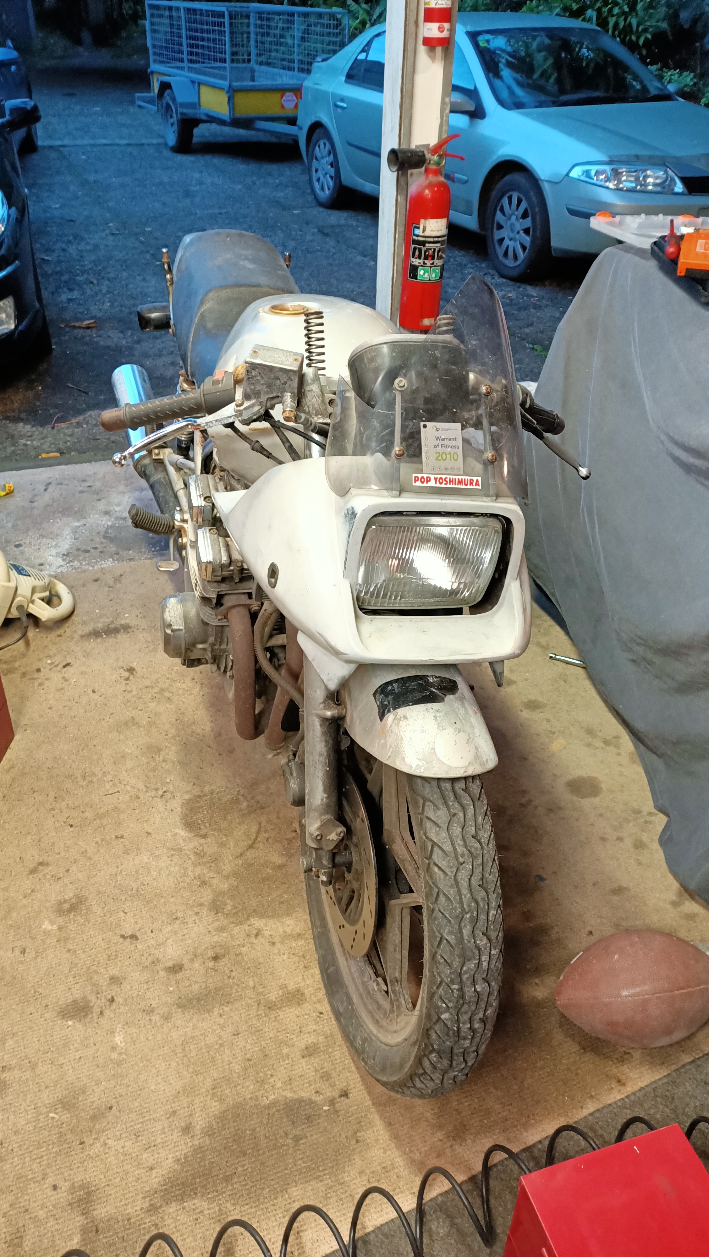
This project is the most ambitious to date. The bike was given to an acquaintance of mine, apparently as part-payment on a debt, and had languished in his garage for a year or two. It was a non-runner and he's not a bike guy. He just wanted it gone and the deal was struck. Here is day it came back on the trailer.
ne8tp1XJHVNKDzG7ytJVsRVAYaFwBmVOJkuhlWhLMaPg8CWkxRdprAoWDuXmB7-6pjlvUKtcbe3lrRbwXMpw_eIAzJxar3PfG04hjDjR3djbuYTEBCrvmH-hgSYOyzZ5kj1nYSGmmA=s0


6M5wtVjPyfpvFeYzy4wxWkccTx7BeKv9Cf1rVCQ9MaOfzr-W0qdxk22LOfFGQ0WwgT4qL5AhBJ5f8kJS1wsIaqvIUBUzLa3Z4IQJ02QoUm0lSg250Q0uXvnPx8WhEpTCQAWNCIoduQ=s0
 
Carb clean, new mains, pilots, and needle valve assembles

e4chDTghxHEK_-rsZXSdBUHb_EnnMc400H0mjwj4yTJGMUhsrKbGi051iDt4dIQy  ztu2nxCEscgCxEmZD1WoJYNtkxoJ5R-CZB-buiJTn5QOdvucyNlNUVRdk5bsfL8F8wVjSgPjdg=s0


Fresh oil and filter and...


Going after at least 10 years sitting idle.
 
Last edited:
So after much sitting, staring and imagining I came up with a plan. The plan was essentially two parts. First is to "reverse the damage" and second to adjust rake and alignment.

The swingarm, frame cradle under the engine, and the frame behind the rear engine mounts and airbox are straight. The bending out of alignment is in the backbone and front downtubes. The triangulated and gussetted area behind and below the steering head appears to have rotated 'as a unit' from the frontal impact. Everything in this section of the frame measures up and shows no sign of deformation or cracking. So "reversing the damage" looked to be pushing the front downtubes back out straight, while applying a pulling force at the bend on the backbone and a rotational force via a lever in the steering head. The deflection and deformation at the points of damage weren't overly much, and I'll probably weld in bracing into backbone at those bend points Pushing the down tubes forward meant removing the engine.

The idea was to build a jig to replace the engine and hold all the engine mounts in alignment as well as provide jacking/pulling points. The plan was to exert enough pressure to push out the front down tubes direct at the point they are bent in, while simultaneously holding/pulling on the backbone tubes until both sections are straight measured against a straight edge. The deflection of the tubes is only 2 or 3?. I have a 10-ton 'porta-power' hydraulic ram to push the front tubes out and have fabbed up two large diameter square thread pullers from some scrap large g-clamps (which also formed the main members of the jig) to hold/pull down the backbone.

SpipjcHiIbqwuoRDqkf_bBeacZ_GnFfKqTjMBD2trgcDtNLSpN_Vl4T_3IbuGyE4KpAZNB5aGEd-fctBh60S0nrF162cZuZcdCIoZTXKmm3EjwVWi05ut0AbmR1pK1ng_ZcfleVUrw=s0


The second stage will be to return the engine to the frame and construct a chassis trueing jig to hold the frame with the swing arm at horizontal (set using bubble levels) and provide pulling points to twist the steering head so the pivot is plum on the centre line and perpendicular to the swing arm pivot. At this stage I'll also measure the rake angle to see if it is within coo-eee and I have a some lengths of square section steel tubing to construct this.

So far the total cost of materials and tools has been NZD $250. Most of this was for the porta-power which was cheaper to buy than hire for a day. I have access to scrap steel at very low cost.

I did some research on the steel alloy the frame is constructed from in order to determine to what extent the straightening will effect structural integrity, and what, if any, heat treatment either during or after the straightening process may be required. I found a reference on line on a Japanese website that described the chassis as being built from STKM13A thin walled, large diameter tubing. STKM13A is a JIS steel standard which specifies steel with a maximum of the following:

Carbon 0.25%
Manganese 0.30% (0.9% Max)
Phosphorus 0.04%
Silicon 0.35%
Sulfur 0.04%

Yield strength for STMK134A tube is 215 N/mm?, ultimate tensile strength is 370 N/mm?, and elongation is 30%. So confirming that is classed as low tensile mild (low carbon) steel and is quite ductile (non-brittle/high plasticity). Good news, as this means that the risk of introducing stress and fatigue through bending and straightening are very low. Being low carbon means that heat treatment isn't required to normalise stress or return material properties (annealing/tempering), basically because heating and cooling doesn't change its crystalline structure. Suzuki using STMK13A makes sense for ease of manufacture. Cut it, bend it, stamp it, weld it, paint it. Done. It also makes it easy to repair. 'Slight' bends can be pushed back. As long as there is no problematic 'plastic deformation' in the tube (kinks, necking, etc.) all good. Other fancy steel alloys like chrome moly require a lot more care, especially with welding.
 
Last edited:
8s1zj6ymEiimf8p-MxZaVWgpagzLYQ1PQ1M-5J_abahbRXwHfqXpNEiXJzNE6swSmI1NggPW8AVg9E0YNjXQIqFAfrR7-J1G0MAqkaBLxd1b3gg4xIipKBFhkTELZyJZ6qkgujgC5g=s0


This was the jig just before applying the pressure

Frame straightening stage 1 - reverse the damage. After lots of looking and thinking about the direction and distribution of the forces I was going to apply I decided that as the push force was down the centreline and that lateral and twisting would be neglible, I wouldn't do much more jig fabbing. So apart from a welding up abottom mount cross brace, I'd just get to it.

The jig it is extremely stiff, so I wasn't to worried about flex letting mounts going out of alignment.

All the mounts where torqued up and the ram and screws were preloaded. I started applying hydraulic pressure checking for deflection of the front downtubes while adding tension through the screws on the backbone. As the front tubes deflected forward, tension on the back bone eased, so I added more tension, effective pulling the backbone down. I added more hydraulic pressure until the front tubes deflected slightly past straight to allow for elasticity.

SHM81lu3LZab_m8DplC3YlnXB0Ug2bB8NVpEnP9JxFelc-65Ov15AhMMjK2_vITe2dFRDIGVmPFq6SO-7gB8hINgJXqHkN8zE3GI5EOOwrL4BqRJzoo8C3mSLby1Qzc-Qc7kP5j2Tg=s0


I released all pressure and tension and checked for straightness. Here are the results

HGA0PooeGQ0B_vEOqby9Gsp4VJPRpD5p5lKNY1EZUD96uHaKYdW8ax3I-LTKiaiSpIHeVkxSwYMyk7Mbzsq9hmgjMAKnj9wV_tHMt-VrLdZ5RsfusjJ_otfT6bgjOUGOelqX-DRvFw=s0


w-X9K0hG_RzKn94nK6Yc3ljLRjUl4v_0P-snkF63mwAxHGHDmntB9tDfthR_arnVAxAJHZ_aPIX60oGj8Ew7eKZlQMT8qDJsrj7rf0CF65uQyx4DyvpzzkqMjqcbCkm8WHIHNhMC_g=s0


8nR2MmRM1U75oYYNNdzlZpjvzE7WLG4Yd2VnbjdZCWNO3uh9fxvTLiPwmFfto1KNy4N454c--p8NXTa4R-Z9FZP72TKkV3IUur6AR2YLFfkyrX-dvZExnpn8TD7TetQXjLc18nm--Q=s0
 
Last edited:
4uXdoqEmAlQEiNg2VZFACGiD_PnEBk0XDaCf4shtpxnC4DpzDKe1k7egR1KOVfDQGxTGdi7MYNQ5CNhAKypgJizW4pmMzMZjhyhu6paxytHtxmd8c2sweCfykDC6xGs_GgM_eK47bw=s0


Everything is equi-distant on both sides and all mounting bosses are in alignment. No cracking at welds. So far, so good.

Checked the deflection on the front fork stanchions (bent) and I think the next step might be to rebuild these with the new stanchions I got for it (cheaper and easier than straightening and re-chroming due to pitting - which cost the same as new), pop in the wheels and check alignment using string/laser. The bent forks might be the cause of the front wheel being a little cocked to one side. To the naked eye, referencing against the horizontal rods I've it on the frame, the steering head doesn't look twisted. Although a small deflection is all that's required. But if I'm lucky, and the steering head is in the vertical, I'll save myself the trouble of having to do some unnecessary jig building.
 
Fork disassembled and cleaned

Gswg0BXDcFFZf3180MVs1lKxQW5Zl-NEvGixERcDssfhbTmPu7tX2Cbi1L2mViQEBQDuT8MphDGoimL7b303cuMA3Tj9fTfYuh_Dd7t1-cGnbeu-WVuZPxoBlVgrlDusbSr4DkzNEg=s0

Out of the parts washer

AYdYA1qeuP8UM7GqtCk6dXC1vokIC1JMdMHJ7sDMKtlIP8s7_4oYLjbV667d_TsozA1ixRXnsoRxEcw_r_d22nlzbj4fKJf594Mhsdshnc07akcikV06Z9FFPJpJdasljD9rFnrfsg=s0

Worn bush next to one from the spares box that dates back to the late 80s...

bNcZemYTziu_GK3v-gSVWDM45HdWM-ZecsebXjTiKx60qHpC74rdBe4z1UY-paP_n6DjL1rnpdMlmp30PDpTTK7-5K3yrJHOon3fnJQbl23o09Fl9BUK31ON7MiH_hOLC8eax2IRAA=s0

Comparison with replacement aftermarket part. Some minor differences, but correct where it matters.

a3iYA_VBNSc3_DGhVhKISHnWI9lkreaxWg2pkG8osn12RS33QWS1XDMnZF7UuQPqquAkM_J98T3g8JwBAiH07dkeIjQaEhshIo7jMG0PUAgFXjo8m87dDkgy68e0JfsO4TtIySnGTQ=s0

Bend apparent on the glass plate.

Next step to polish the lower tubes. Drill the damping tube orifices - I have a set of fork cartridge emulators I was going to fit to the 1100, but I think I'll keeping her as standard as possible. So into the 750 they go.
 
Reassembled the forks. Replaced the worn bush. It needed a little filing of the end gap of the bush, as the insufficient gap meant the bush sat proud and the fork tube couldn't be inserted. Set up the cartridge emulators with blue springs and 3 turns reload, which is baseline for the Katana. Fresh seals and 10wt synthetic oil, emulators and springs in and the fork caps won't go in deep enough to bite the thread....

Upon inspection the alloy sealing buttons are binding in the top of the fork tube which has an internal taper up the top starting below the threads. Measurements with internal and external calipers revealed the difference was around 0.1mm so the aftermarket tubes have slightly thicker wall thickness.

The easiest fix was to reduce the diameter of the button by 0.1mm, but I don't have a lathe. So I came up with a solution with what I had to hand: plastic pipe, some wooden dowel, tiny panel pins, hand files and emery paper. The buttons are essentially static, when fitted, so while roundness and clearance is important, precision tolerances aren't required.

8zlQ8MU6Wc6asxDJD7wbRWpu72HtLJ0HmziZ2ewP0x2ewhP3Dop4VIIdcrx_0E8umlpTA7U23QggOglh9XI6sH2TspmoOYrd1LtbpkybQufY45PxtXeMnr_AQOCCGs--zd3l23XI1w=s0


J7Nt4SxQVNP4Dh4LaR-jmCb6hb3JH2K6ypur7QSjPJ3rnYZ2tT-GJg24uXxNQ87PP2v_xRUm-DxKJ8nvbnhZnJOeTOjzEdFN-Uere4koJhKbc4A1OJibpXeRYj-N9B6fynkK25V7vg=s0


meKGAqqU1_Dy_L7utxSAdDWQJit3Rbcc9cbZItReLmXxefrqA5HLmhW-o9eJe-ycSRlixh4i7sR04lP9PoYwYOPjChd3iZqUSdUq2OXAxrMQlYI6rTIGJTveYIXC9dmWO3kIXnVIRA=s0


Kept taking off fractions until they fitted the tubes and the caps could be screwed on without resistance. Reused the standard orings as they were in good nick and had enough give not to jam or twist. A little rubber grease for assembly. Tested action of preload adjuster, and all good.

1Cc4NBb6HZbSEEk_42NbEUxnKwLLPB-PNuXVA2gCHw7EfUT9ja6_gmykgUgRigHw6cwB9ocdGHNginz3l6cCui1WzJNz-EgxkiieHZht0Ek5vb0ya_OhrdKblo6jbVPyeV7HFHFEcw=s0

Done
 
Last edited:
Teh_T1VEW5LncMepW0NGc-cB4I7EA9u3rZBxKJ7xMcfk-sD7fOwdmAbtXATyi13f5mydYqUEKJCBg3_J1a4bqSnyxtZxhPmPfYBj1QNTJ-mqrByNbq2MUk8CkOwFUUaImAYwtOEz8A=s0


Wheels cleaned up better than expected. Tyres were a bitch to get off. Ended cutting the front one off. Hard old rubber and cool temperatures. Next step to get the wheels and frame bolted together and run some strings to check alignment and then decide whether to build the straightening jig.
 
Straight forks fitted and tweaked steering head confirmed. Next steps degrease the engine, build straightening jig, refit engine and reset the steering head.
nejK_ZnTgF3blLdDxRtAompDd4y4DrKNtkxcb7IcxPN2EHTTXvAa4QPSNSbntkQVqng6EOdB48dGiolJ3mQqSxehlyZODQrvAkZ50M9OU3ltC5SuUoxcQN9ODAcSbi2p8W2224jLiw=s0

7zHt0ea7cWp4VeDhL6gHqyiypVHUNWpC1OhFPFFA-79NilMpf80WBUtJxqNvP0PI4n0SWbHnOzmoZqsc59YU1gs0J2Iod4e0DOotfov_xmZpftqiDjj6vRQzX0dffuygJ5tr9Yv1vQ=s0
 
Last edited:
Frame jig 2 is coming along nicely. Used a plumb bob and spirit levels to centrepunch some centreline reference marks on the frame and swing arm. The datum was string lines off the sides of the rear rim -checked square against the swing arm piovt- and pleasingly this mapped the exact centre of the swing arm pivot and frame cross tube. Did some diagonal measurements between front engine mounts and the swing arm and they were identical I have confidence that apart from the tweaked steering head, the frame backward from there is straight.

FZ-6nirqp1JJjj16-houP2vR2MWJaJ6juOandtKq7vlyx_WmGz6JZiLpwgdMwan5EYzNoh-Ta8j_RjwbuEJc30BP5dVoSPDVTpfCQxpXsotwpPtjjd3YcTA_UwOkU74npvEvU66pSg=s0


So after some more sitting, staring, and imagining the forces I'll be applying and paths of transmission, I cut some steel and did some arc welding. The chassis with engine bolted in forms the rigid mass for the jig frame.

It5DUksErt0gO1sbFF7ICcSyPSI09vSiSgQe0o4cpFpFQ4IUoreVH5BveG4o2DIn-Idhv_snTCUT9VmAZJrMZ_fdoBFB3zO31opLdieY4G3jglKaUm2wCcJ5D0aks4n6vSJoMCtGlQ=s0


I'm going use my push ram as I can't get a pull ram under NZs lockdown. There will be an arm for the ram to sit on and push a heavy tube dropped through the steering head. The idea is have the ram operating as close to the horizontal plane of the jig in order to increase leverage on the steering head and minimize leverage and torsion directed through the jig. There will be some triangulation to resist the main jig beam bending.
 
Last edited:
Jig pretty much finished. I have a crossbar to fit to which the ram will push at 90? to the centre beam.
JHRDgOORFi2QS8zv1wfRd9GeArK2lHtnkKw8IcYuMmrUxS_buVYmG0t_XJEqyklXAjfFi3UCe2UG9-mGizfVpq9cwDsU8JtxaSauNWnCkfcAnYER24ylkF1Im2p9ntxRnEko4paB_Q=s0


Final checking will be front axle centreline alignment. The defection is approximately 15mm at the axle.
vQBZD8mekJvLz5xgfT8dNGWGu7MljyDiYMt1PZfCDelfKZG4_KOF6h5mUWVjys23srGYrsz8XVRbb8UpnJq6GfRGErPpjIS76iH-uvfUSs5tBRgT9KXHYmHGuJGJQXI7nmf8Fwg8eQ=s0


I've begun pulling down the top end -which was always part of the plan- to make fitting and removing the engine easier for the straightening process.
mPTnrmA26FZfyA9FHL_Ee60E4Y5G1jDSyYm3miAmhbIXUawpktppkJkvdtKYs1IVhMGGpaJVcxA2BIHOF8cAM0YT3OQsXirKKA22qJmwhC0I-l_Oilbed80U2YnV0Ah4UQwveT1ltg=s0


Already a few issues have become evident
STDBG8Ee30u7-jPJg5ex4oeg9wsv1QDejaQL6FRteBbUK9gJeWqfv3fKGCJ3Eyu_JwxDeVBCWNXN7mYdqEpGH178HqVFCC3ZYGkSNel64G0YlKjl7BN8qZBmHn0dm03mwd329i84Rw=s0


Inlet on number 2, is number twos
jYveHXyiic8QwRGFGICz6PeM6jxGjtKnI5iruxHsF6AwrlDn8TjAabNKLnX3CHvEDsN3UczA1Gczviw4X_GQuLzYSHgd75sEoh_xFTlLff7Rr8PnneTKh-M3CDP9rIAfNuroONZWHQ=s0
 
Did some research and the 1100EZ inlet cam has the same part number as the 750. The sprockets are different. I thought I might have one in a parts box, and found a match. I also found a matching exhaust cam. Both hare in better condition on the lobes and journals.
Just need to swap the sprockets.

Thought I could use a spare 1100 rocker arm, but of course the 1100 and 750 differ in valve stem spacing. So I'll have to source some of those...

DGfTFpd9ZmVbvyhU3vXC4Z3X3aojHk-rpcGOZy4fiSqYbckgD4s07YK1Ru_2s-VNyL4DG91HBQRQeyw6wZtB5OE9pPZ9BrOnW16mfew1coKjxGp-df-5UHoMZEW6u9xFjHv6G5Mvxg=s0
 
Last edited:
Ej4nqZxT6ITuO4kuHkwjQaUp1BlF3r8olhvAekVn5HXjt1oOWEvnAE_3kxamSW6a2uZj7TYSGDpbGEAUJMyJ-KnkeN1arzndygbm2aNwx9DZu8jvRk-_n6VjLmGFdNDlXVkGC_7BYA=s0


I thought the screw that goes into the top of the nut was stripped, but it was the entire stud spinning. At least the PO left it in there.

Looks like the existence of the torque wrench was unknown to the PO....
 
Last edited:
Seems that the torque wrench comment was truer than I'd hoped for. All the other head nuts where so tight I had to use the half meter+ power bar to get them loose, while basically standing on the gearbox. All good until I found two of the 'dry' head nuts had been to rounded probably by being over-torqued with the wrong sized socket. It took tapping in a 9/16" impact socket and and using my gruntiest 1/2" rattle gun. Even then it took a good 20 seconds of hammering to get them to move. The last one came out with the stud attached... I'm going to have to check the remaining studs for necking.

UOiXZ3MTjlqq-IeVTjxejaED0FBKoq_DaVXVKb7Z5QW3PJ8_bfqUhVHfLAdDrKM-RzARTbAjwmXarZ43qDZtRrwJj9tCetZZ_o2A1arlmIcSyFGzSUIbb8Wj3MV__GThezijseEGCg=s0


AjrVwUQDPB5hlJkZPFtYv-A99iiEAPstQG34sRyP56CeTYA1Oq9IlTxtbaotYx7SK1Ejk0Djc3sXgcPvSWNatF7oJfWi1HoWHDyZMFrc8o_PIYbUSLa9fXANDFQDzZQ4yobqI8JlUA=s0


-6hoMvXHqVtbmcyYuG5P5pzKksZYDkOQdms_4JOvHNxL9l_YgtUVSGjaV9AWJHZkfNlUGe4BPSOk8ZknxtWOoNhcwEPZ_-P9pX3115N-T_4eKkXcAppKCAvN4iUKdNsp09f-MAhHAg=s0
 
So.... I thought I might measure the squish clearance before the head and barrels go (eventually) to the auto engineer for a skim. So I placed some some solder strips in the front and rear squish areas on top of the piston, put the head back on -as best I could- and turned the crank to squash the solder. It seemed to spin too easily and I noticed the cam chain wasn't moving. Took off the ATU and found this.

Wtd_4xo8R5CbVRO9FcXxNrVWSPKeKTr1urh4kh_ve6Yk-LUd_O-fmPlE8UKO4VCTDUw2Olbgvb7H4a7DTB_cHmi7O3WOkkg2V1AvK5ClgXvHbGdUunSEcezJjFCASa5VoHSFSvG8pg=s0


Seems the drive pin was replaced with a small wood screw and a load of crappy epoxy.

5akgnV3x7H06eRUlJTMy64cYtN3yoLoevECCP-mtFG-RJk7akGXmHT9kC_IJYZWi1jyT66WK8gU376hDYODAw5CW1-6g10zgBscQ7YGhXdBI_QEjTojLBPY8NJyVv7MXUOyH3wE-sA=s0


Looks like the remnants of the pin are still there as a drill doesn't cut it, so I'm thinking it's tool steel, which the wood screw wouldn't be. So out with the diamond burs I used to get a broken ezi-out out of an outboard motor.

__bWD04TFqDcOspD4z8V_TnS_QhVj6Qeqg82OBAe6H6-QKPOQa5pvLgy1t0DjklYr7UCzCjmwUohRcnrjuX_4GxNfeIgP5HuVJH9MZRsHvOvOwPwYgzd23tWs8dz7V-75M8f_xnGsQ=s0


I think I might make a pin out of an old drill bit. The slot in the back of the ATU is 4mm. It should be plenty strong enough as the pin isn't subjected to shock loads.
 
Back
Top