• Required reading for all forum users!!!

    Welcome!
    Register to access the full functionality of the GSResources forum. Until you register and activate your account you will not have full forum access, nor will you be able to post or reply to messages.

    A note to new registrants...
    All new forum registrations must be activated via email before you have full access to the forum.

    A Special Note about Email accounts!
    DO NOT SIGN UP USING hotmail, outlook, gmx, sbcglobal, att, bellsouth or email.com. They delete our forum signup emails.

    A note to old forum members...
    I receive numerous requests from people who can no longer log in because their accounts were deleted. As mentioned in the forum FAQ, user accounts are deleted if you haven't logged in for the past 6 months. If you can't log in, then create a new forum account. If you don't get an error message, then check your email account for an activation message. If you get a message stating that the email address is already in use, then your account still exists so follow the instructions in the forum FAQ for resetting your password.

    Have you forgotten your password or have a new email address? Then read the forum FAQ for details on how to reset it.

    Any email requests for "can't log in anymore" problems or "lost my password" problems will be deleted. Read the forum FAQ and follow the instructions there - that's what we have one for...

  • Returning Visitors

    If you are a returning visitor who never received your confirmation email, then odds are your email provider is blockinig emails from our server. The only thing that can be done to get around this is you will have to try creating another forum account using an email address from another domain.

    If you are a returning visitor to the forum and can't log in using your old forum name and password but used to be able to then chances are your account is deleted. Purges of the databases are done regularly. You will have to create a new forum account and you should be all set.

81 750Kat - GS1150 ignition upgrade - recommendations please

  • Thread starter Thread starter Guest
  • Start date Start date
G

Guest

Guest
GS1150 ignition upgrade - recommendations please

1981 kat with 1150 engine
Kat wiring loom modified to use 1150 EFE igniter / CDI

Right the igniter appears to have died so i am looking at a ignitech replacement $157 USD

I thought that I would upgrade the coils and leads at the same time.

what is recommended?

Dyna green coils 3.0 Ohms (DC1-1)
Dyna ignition wires 8mm suppression core gray (DYDW800)

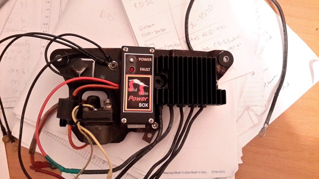
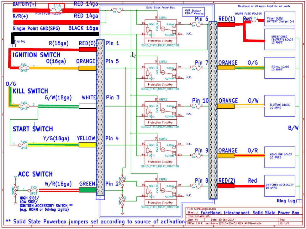
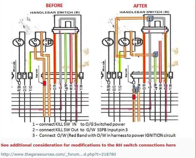
planning to do the starter relay mod also when fitting the solid state power box unit I have.

Any recommendations ?
 
Wow those ignitech systems are really cheap. I would get one of the programmable ones. They are about 1/10 the cost of a Dyna 2000

http://www.ignitech.cz/en/vyrobky/tcip/manual_sparker_tcip4_v88_en.pdf

they claim to provide all of the connectors to modify your harness.

I like these better than Dyna stuff although that is mainly due to appearance.

http://www.powersportsuperstore.com...vzlBJT60aCZK44mW6Iu_h0BoCN93w_wcB&Click=35177


SSPB has a headlamp cutout and coil relay mod incorporated. Just follow the directions.
 
Up grade is on its way, compu-fire purchased and I have started to install the solid state power bow. This thing is a piece of work well done to posplayr.. I am glad I purchased two units. Yep its taken some time to get round to fitting them but here we go. Slight handicap, cant understand wiring diagrams but the tell how to video certainly helps. Still need to purchase the cols and leads, got the ignitech stand unit. I might regret this but the mighty dollar rules. This engine will be 1230 next build.

Here is the mock build so far, and I like it. Plan is to spray lacquer over the solid state power box to save the sticker, any one see issues with that option?
Please comment on recommendations.

20161015_164119 (Large).jpg
 
I have more stickers if you need. A light fogging to deal off the sticker will help avoid any lifting of the sticker from solvents. Honestly have not seem any of them lift.

shot me email on wiring SSPB for any questions.

P.S the picture is cut off.
 
Last edited:
20161018_195730%20Large_zpsc7mbjst2.jpg


Do I need to attach the green wire?
I also have heated grips and radar detector, should I connect them to the SSPB? If so how?

I still need to do the kill switch mod.

20161018_200015%20Large_zpsajlmrdhq.jpg

Extra earth added to corner of the R/R as per the video's which I might add are very good and help a lot.
 
I usually would recommend hooking the GREEN to the W/R (old stator headlamp loop) as that is now a spare wire running to the front of the bike/headlamp bucket(see diagram at Pin 2). You can then connect W/R to a handlebar switch to turn on the radar or other accessories if they are hooked to Pin(8) Red(2).

If you do this externally, make sure teh jumpers are set correctly inside of the SSPB for how ever your switch works (High Side, Low Side or IGN internally controlled). For a RAdar and heated clothing it is probably High Side.


Functional_Interconnect_zps96a0adb9.jpg
 
Last edited:
OK kill switch mod done.
Now not all is good, the SSPB is all good it's the wiring mod in the kill switch that gone bad.

Turn the key on all OK, hit starter button and nothing.
Turn light on and no head light. Switch kill switch from run to off and...head light comes on!
Being an NZ model the head light is not on all the time.
Any ideas where to start, I followed the wiring diagram from what I can see.
 
When it comes to wiring diagrams I might as well be looking at Chinese writing, they are completely foreign.
Saying that following your videos and it was a easy to install the SSPB, I have wired up garages, installed circuit breakers etc. What I am trying to say here is tell me what to do and I can do it, but read and diagnose a wring diagram and its a no go.

So lets break down the kill switch mod.

wirring%20diagram_zpsa7wsv8ds.jpg


I started with Mod 3 - O/W wires from the wiring harness to the kill switch - cut and join. You can see the two O/W wires joined.
20161030_165704%20Large_zpsrkhut949.jpg


Next came Mod 1. Take the O/W wire with the red band from the loom and splice it in to the grey loop on the kill switch that goes to the O/G wire on the loom.
The grey wire has been extended hence the join in the loom Y connection.

Done this.

20161030_165753%20Large_zps1biskrqd.jpg


Last Mod was number 2 - take the other O/W wire and connect to the L/W (lime and yellow?) wire. Its the one to the starter solenoid?
this is where I may have gone wrong?

Or should this be the white and green stripe wire?
I did not want to go any further with out asking the question.

20161030_165747%20Large_zpsjxpbhmcp.jpg


I'm hoping Posplayr might have some ideas, anyone else?

Thanks
 
So lets break down the kill switch mod.

I started with Mod 3 - O/W wires from the wiring harness to the kill switch - cut and join. You can see the two O/W wires joined.

Mod 3 is connecting two wires on the Harness side. O/W with red band to O/W without red band. I cant tell from teh picture but your words do not say you did this.

Next came Mod 1. Take the O/W wire with the red band from the loom and splice it in to the grey loop on the kill switch that goes to the O/G wire on the loom.

The grey wire has been extended hence the join in the loom Y connection.

Again the words are wrong, Mod 1 powers the kill switch from switched power which is O/G or the grey on the switch side of the connector (opposite the harness).


Last Mod was number 2 - take the other O/W wire and connect to the L/W (lime and yellow?) wire. Its the one to the starter solenoid?
this is where I may have gone wrong?

Or should this be the white and green stripe wire?
I did not want to go any further with out asking the question.

I'm hoping Posplayr might have some ideas, anyone else?

Thanks

Mod 2 clearly connects to the Lg/W as shown in the schematic. The Lg/W is a spare wire now that you eliminated the stator headlamp loop in your R/R conenctions.

In the schematic below G/W is Lg/W; somewhere along the line Suzuki started designating G/W and Lg/W.

So near the R/R there will be spare wires coming out of the harness one is Lg/W and the other is W/R. Wire the Lg/W to pin 3 (White pigtail on SSPB Molex 10 pin)

Functional_Interconnect_zps96a0adb9.jpg
 
Back
Top