M
mlinder
Guest
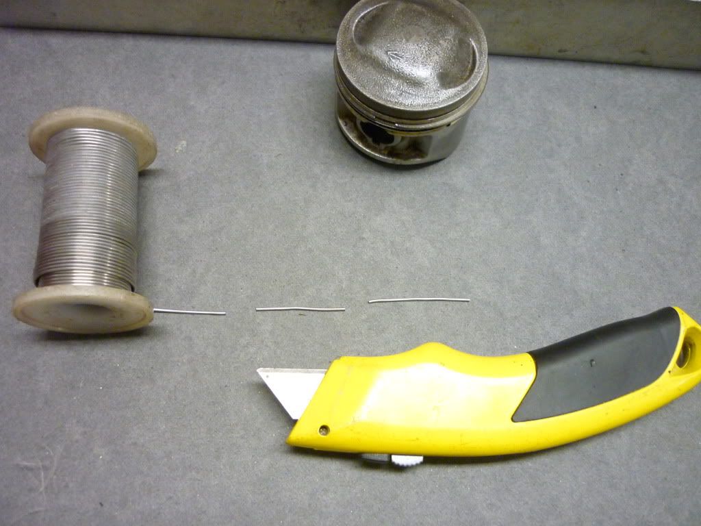
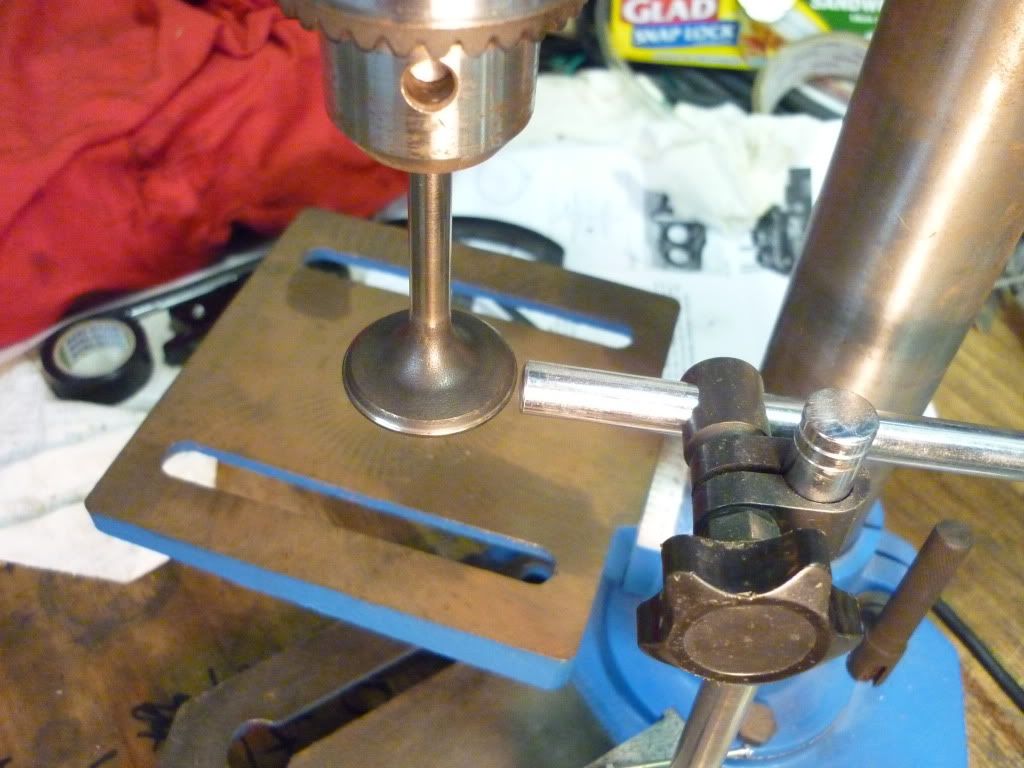
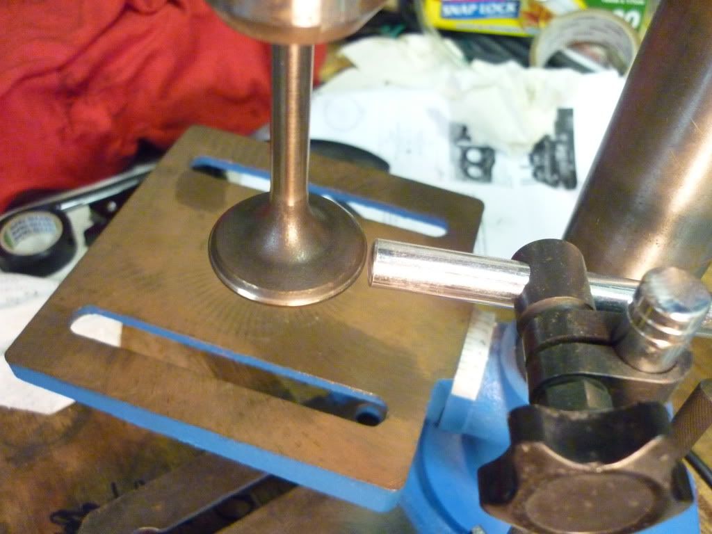
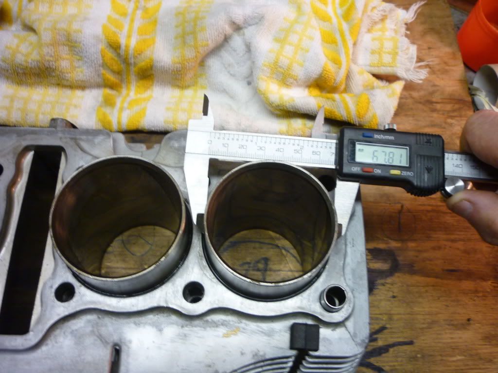
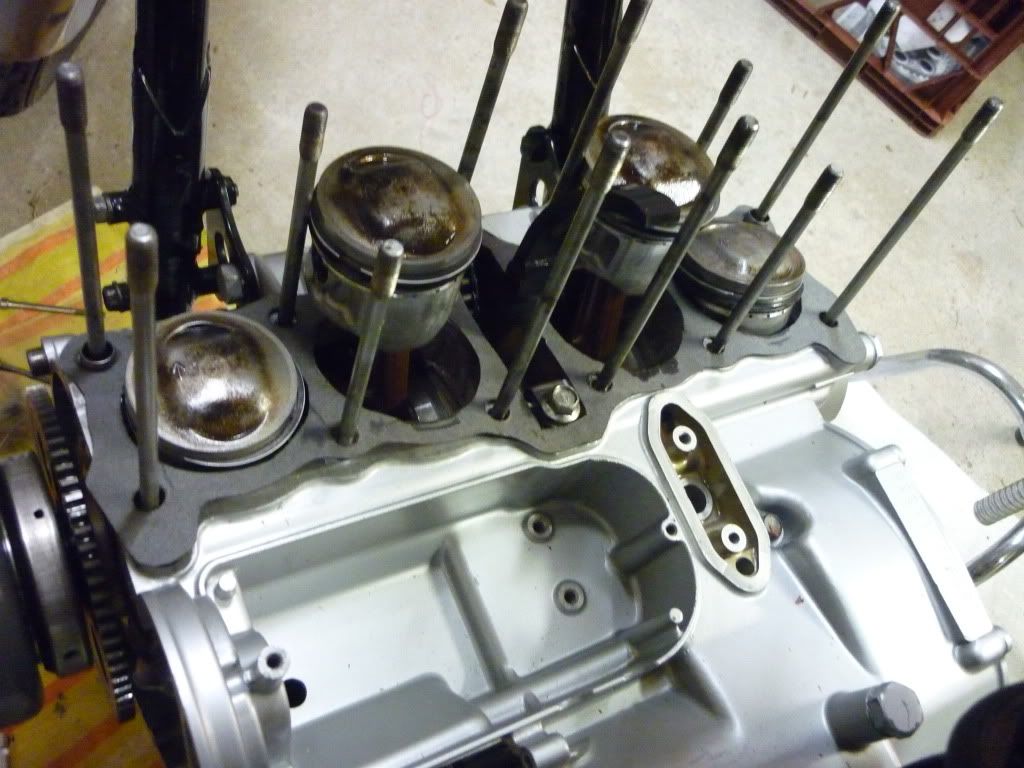
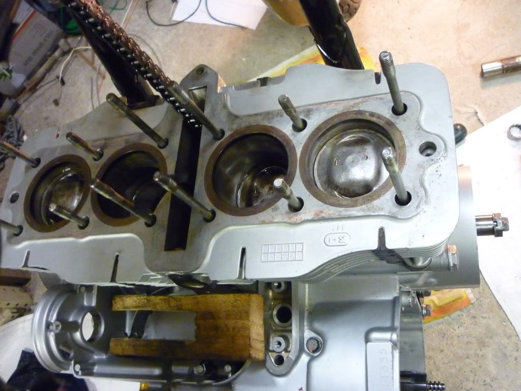
I'm not sure why you need a dial gauge, but you could measure piston height to deck with a good mic. Hampshire explained what Billy meant about measuring at the wrist pin.
Required reading for all forum users!!!
Welcome!
Register to access the full functionality of the GSResources forum. Until you register and activate your account you will not have full forum access, nor will you be able to post or reply to messages.
A note to new registrants...
All new forum registrations must be activated via email before you have full access to the forum.
A Special Note about Email accounts!
DO NOT SIGN UP USING hotmail, outlook, gmx, sbcglobal, att, bellsouth or email.com. They delete our forum signup emails.
A note to old forum members...
I receive numerous requests from people who can no longer log in because their accounts were deleted. As mentioned in the forum FAQ, user accounts are deleted if you haven't logged in for the past 6 months. If you can't log in, then create a new forum account. If you don't get an error message, then check your email account for an activation message. If you get a message stating that the email address is already in use, then your account still exists so follow the instructions in the forum FAQ for resetting your password.
Have you forgotten your password or have a new email address? Then read the forum FAQ for details on how to reset it.
Any email requests for "can't log in anymore" problems or "lost my password" problems will be deleted. Read the forum FAQ and follow the instructions there - that's what we have one for...
If you are a returning visitor who never received your confirmation email, then odds are your email provider is blockinig emails from our server. The only thing that can be done to get around this is you will have to try creating another forum account using an email address from another domain.
If you are a returning visitor to the forum and can't log in using your old forum name and password but used to be able to then chances are your account is deleted. Purges of the databases are done regularly. You will have to create a new forum account and you should be all set.
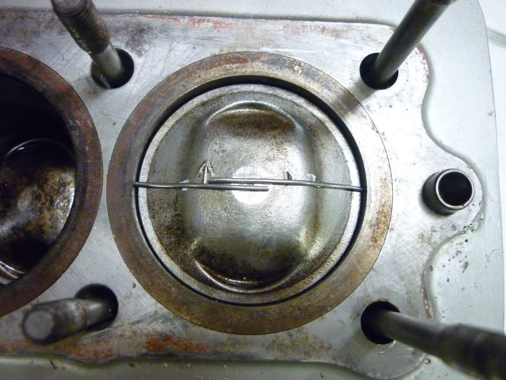
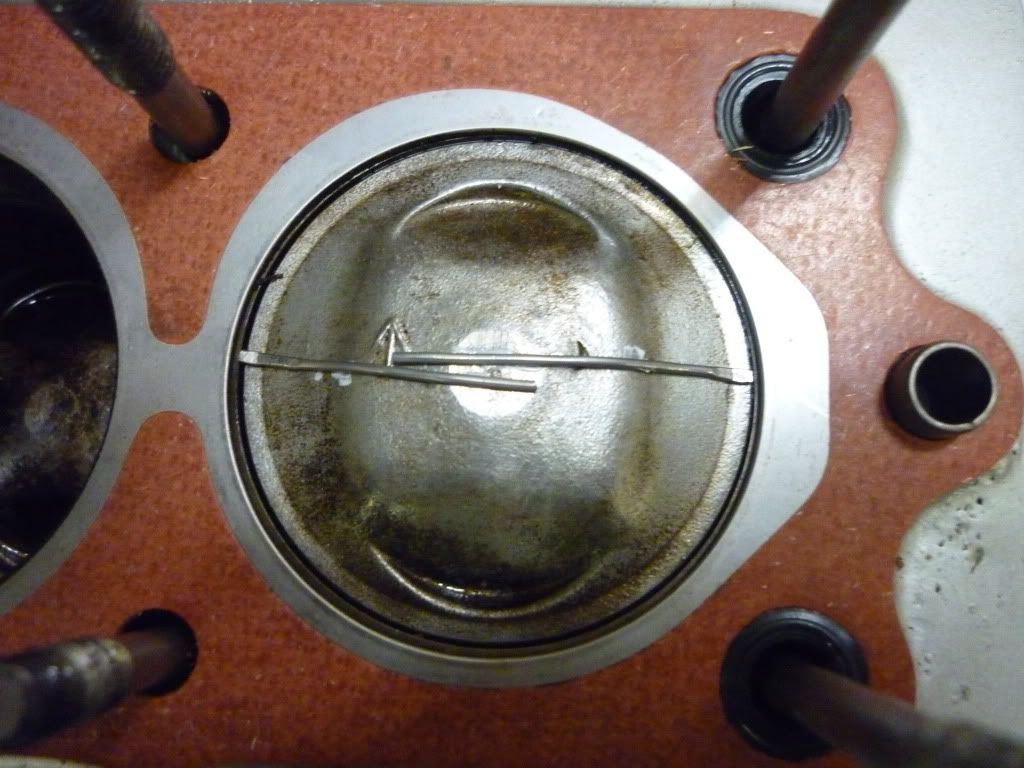
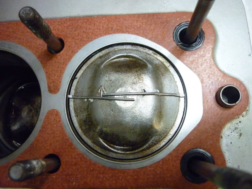
Hey Don, nice work measuring the clearance...BTW, how much is there?
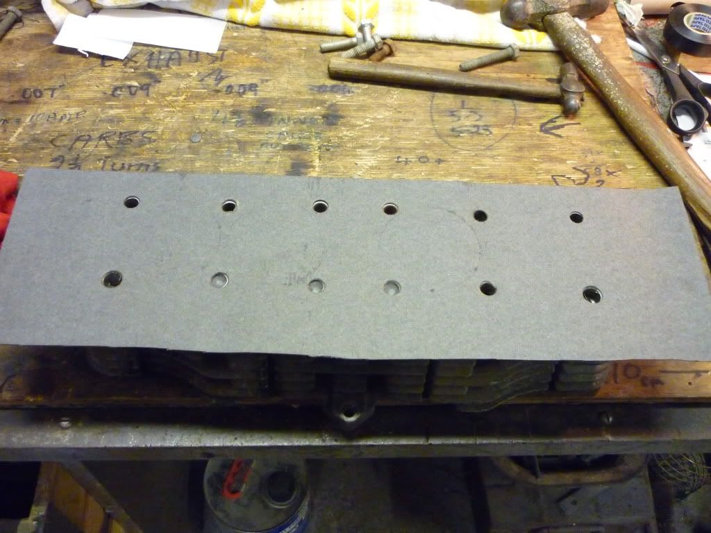
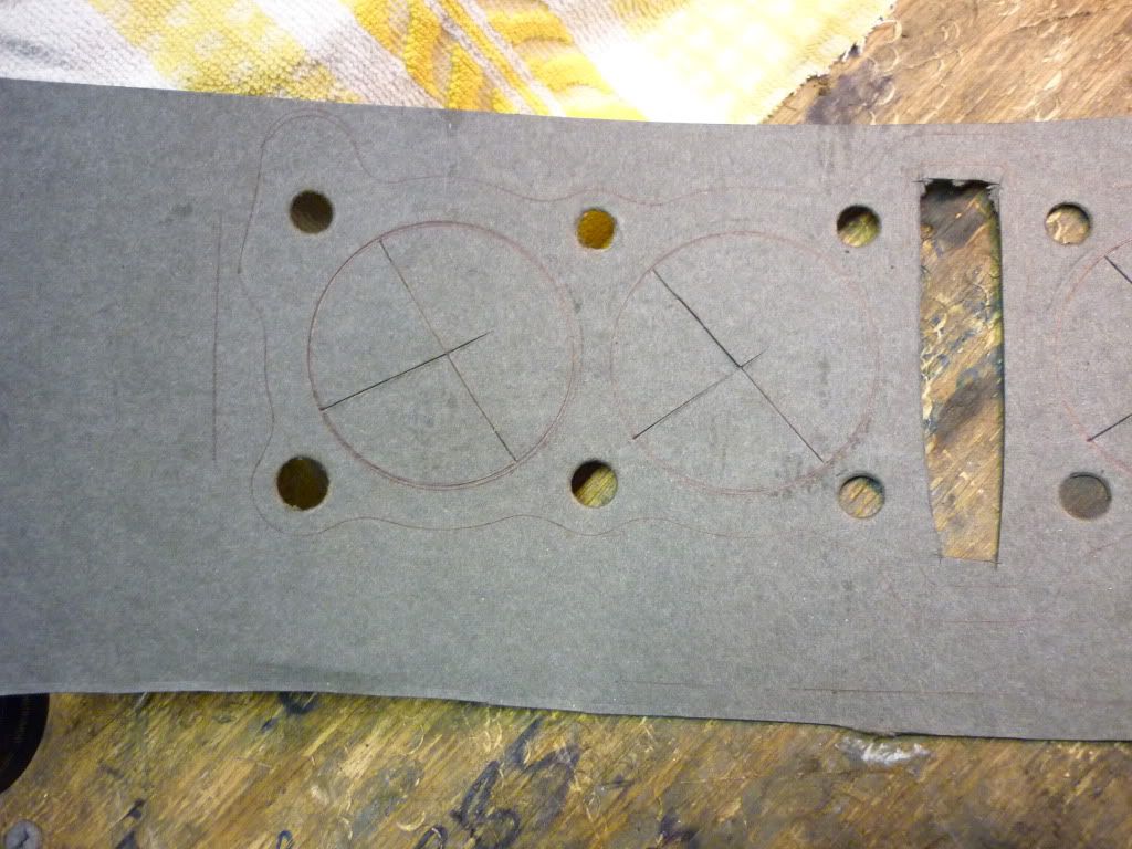
After my experiences with base gasket failure with the Athena gasket material I'd be leery of cutting my own gasket for that application unless you can be assured you have the proper stuff. Sorry to be negative, and let me know if I can help you in any way - shipping you a gasket for example.
Typically the failure would be from the gasket shifting or squeezing out. I like to install them bone dry with clean surfaces both sides. The tendency varies with different gasket materials......BillyThe cylinders have quite a large surface area that bears on the crankcase so wouldn't a gasket made by myself work OK. Where would the oil get through? How would the gasket fail?
")
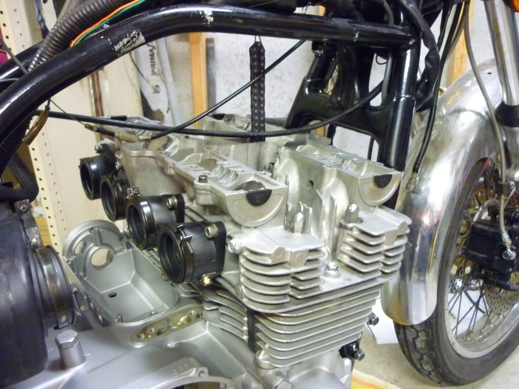
So Don, hows the re-assembly going?
I'm glad you ran into this problem before I did so I make sure to check.
Keep us updated.
Hi Don,
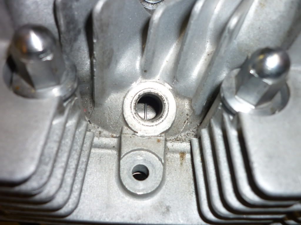
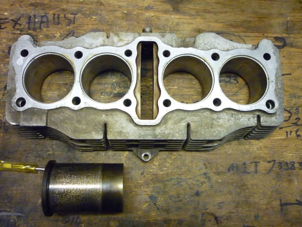
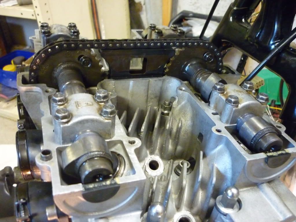
Was looking though the parts fishe and apparently Suzuki did away with the cylinder head chain guide thing between the cams in 1981 for the 550 and the 650's never used them. Think I'd ditch it but the call is yours.
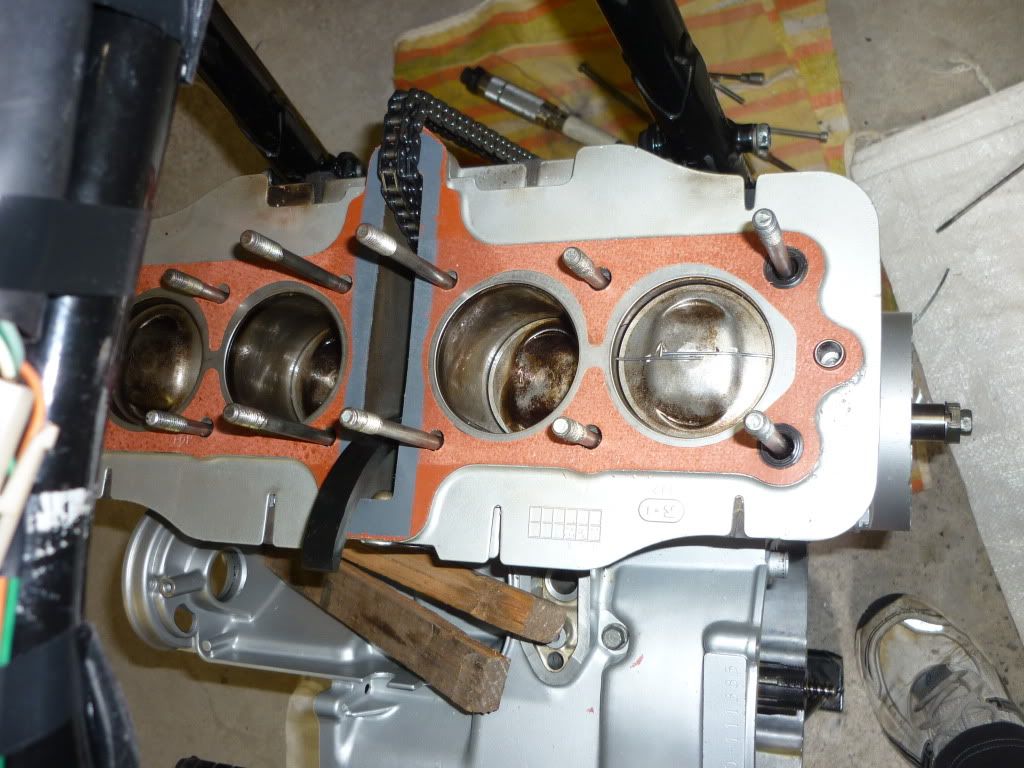
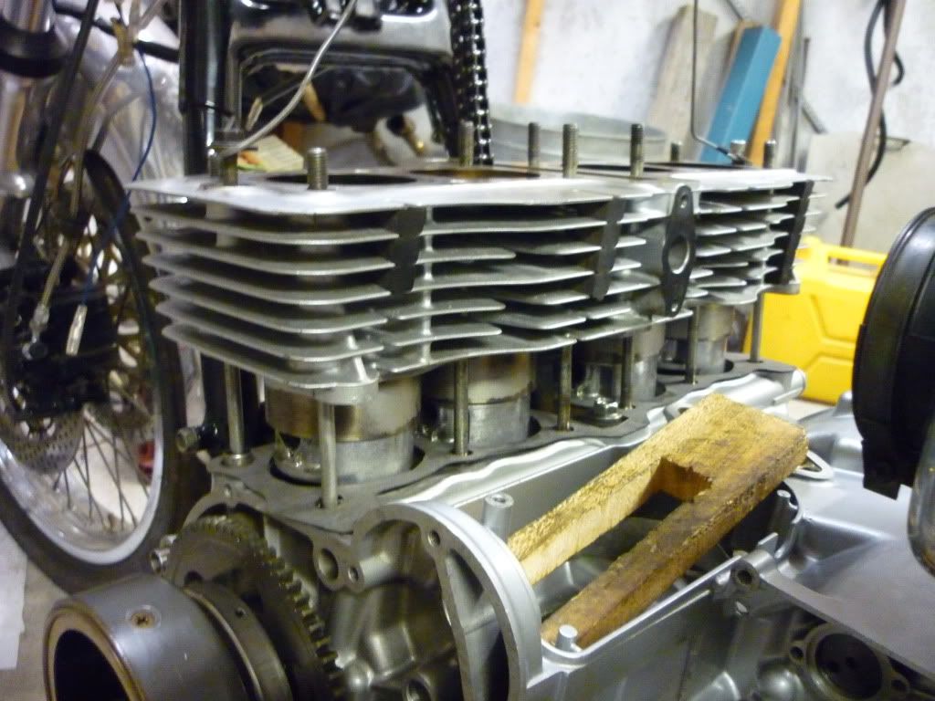
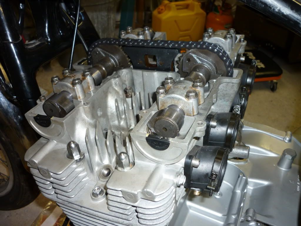
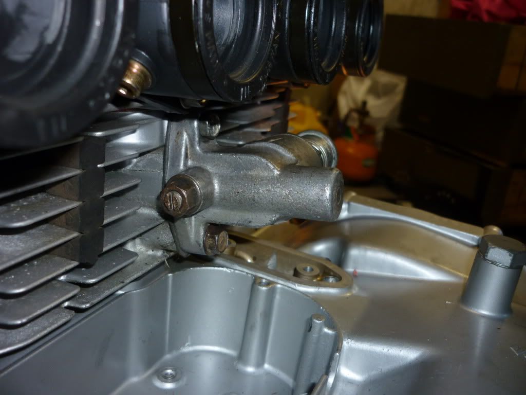
Hey there Don, good to see you making progress. Maybe you could give us a nice camera shot of the end of the camshafts from the right side of the motor. The slot cut in the end of the camshafts should be parallel to the valve cover surface on both cams. It looks like in the picture above, 3rd from the last, that the intake cam is retarded by one tooth.....Billy