• Required reading for all forum users!!!

    Welcome!
    Register to access the full functionality of the GSResources forum. Until you register and activate your account you will not have full forum access, nor will you be able to post or reply to messages.

    A note to new registrants...
    All new forum registrations must be activated via email before you have full access to the forum.

    A Special Note about Email accounts!
    DO NOT SIGN UP USING hotmail, outlook, gmx, sbcglobal, att, bellsouth or email.com. They delete our forum signup emails.

    A note to old forum members...
    I receive numerous requests from people who can no longer log in because their accounts were deleted. As mentioned in the forum FAQ, user accounts are deleted if you haven't logged in for the past 6 months. If you can't log in, then create a new forum account. If you don't get an error message, then check your email account for an activation message. If you get a message stating that the email address is already in use, then your account still exists so follow the instructions in the forum FAQ for resetting your password.

    Have you forgotten your password or have a new email address? Then read the forum FAQ for details on how to reset it.

    Any email requests for "can't log in anymore" problems or "lost my password" problems will be deleted. Read the forum FAQ and follow the instructions there - that's what we have one for...

  • Returning Visitors

    If you are a returning visitor who never received your confirmation email, then odds are your email provider is blockinig emails from our server. The only thing that can be done to get around this is you will have to try creating another forum account using an email address from another domain.

    If you are a returning visitor to the forum and can't log in using your old forum name and password but used to be able to then chances are your account is deleted. Purges of the databases are done regularly. You will have to create a new forum account and you should be all set.

Completed single point ground

glib

Forum Mentor
Past Site Supporter
I almost got stranded 40+ miles from home yesterday so once I got home I got busy and completed the single point ground and checked every other connection I could see. There was a white/red wire which had become unconnected but I'm still not sure where it goes. I repaired it and got the following numbers with the quick test:

Key off: 12.74
Key on: 11.74
1500 rpm: 12.55
2500 rpm: 13.60
5000 rpm: 13.25
Key off: 12.98

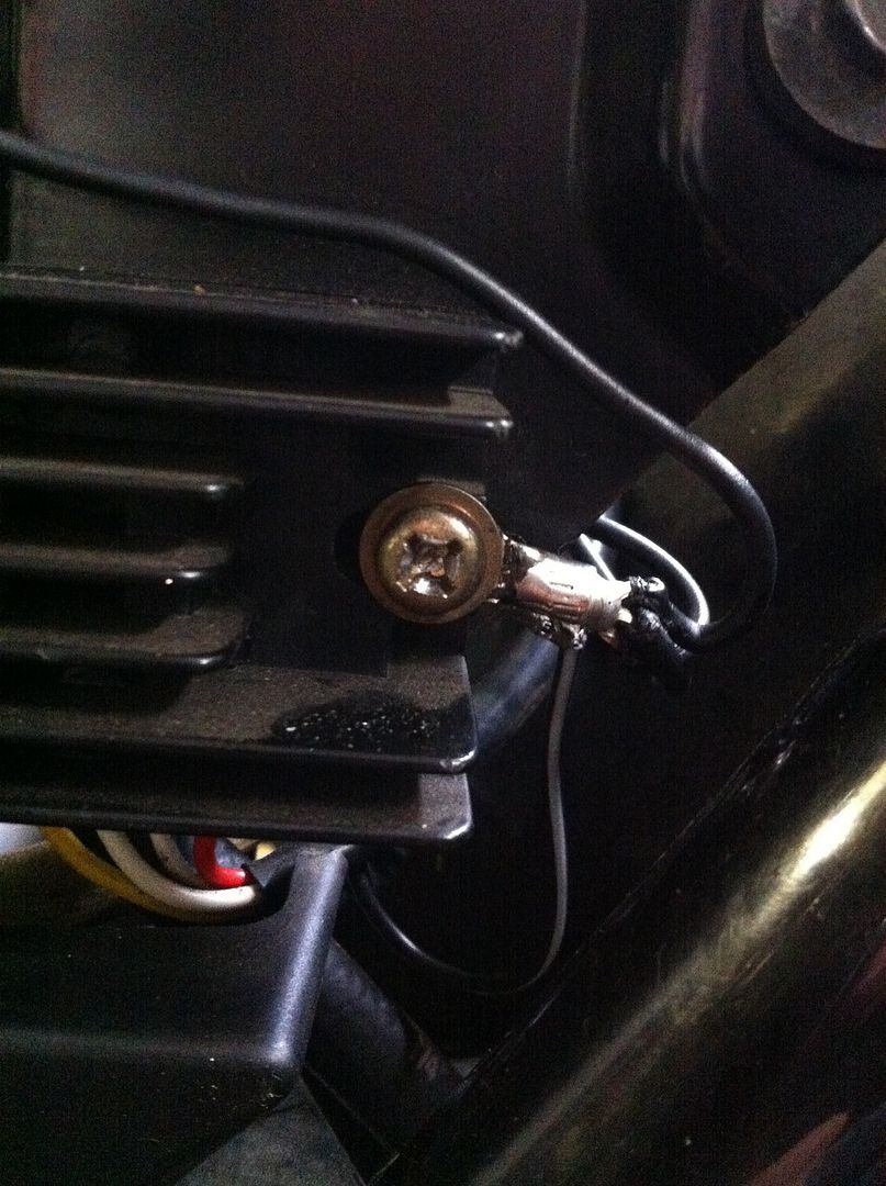
I believe I was quite careful to follow the instructions with the single point ground, soldering the connections. The ground from the R/R was about 16 inches long and ran to the starter solenoid bracket. I shortened it to about 4-5 inches and ran it to the single point ground which is on the right side of the R/R. The other SPG wires run to the battery, frame at the front of the battery box and the starter solenoid bracket.

The "key on" number must be telling something but I don't know what. (Edit: I guess that means a weak battery. It's only a year old. Any other way to test it? It is not the one that was in the bike when the charging system failed--that one is on the charger...Um, the water in the battery is low also.)
The "5000 rpm" number is pointing to a connection issue if I'm reading the directions correctly but I am confident about the SPG and I couldn't find anything on the positive side that looked suspicious but I don't really know where to look beyond the battery and panel area. (No corrosion on the fuse box--applied dielectric grease).

SPG:


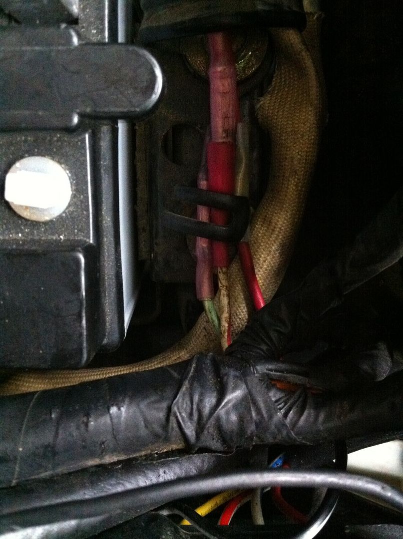
The two wires I repaired have the transparent pink connectors:
 
Last edited:
Well I'm glad you posted some pictures about what you are doing.

1.) Yes it would appear as if you still have connection problems. Do the Revised Phase A tests at 5000 RPM to confirm that (measure voltage drops). Your voltages could be a little low due to the battery being a little low (result #2) but the lower number (#5 than #4) means connections.

2.)You need to chemically clean contacts and especially inside of the crimps. One of the problems is that you are NOT using flux and so you are getting your wires WAY TOO HOT and you are melting the insulation and getting way TOO much solder wicked up into the wire.

I'm not sure of your wire sizes but if I could choose I would go 14 ga for the R/R(-) from SPG and 16 ga for all the rest.

Also you should support those wires with some shrink tubing. As it stands the wires from that SPG will probably be broken off in 6 months. Remember what people say to not solder connections? It is because it stiffens the wires and they tend to break off.
That is why you only want a small amount of solder to bond the copper wire ends to the ring lug. See the picture below. This has not been soldered yet, but the plan is to only solder the exposed wire ends to the ring lug and then slip some quality adhesive shrink tubing over the top.

SPG.jpg


products link.

http://www.thegsresources.com/_foru...-Preparing-Electrical-Connenctions&highlight=


I hope you wired the stator direct to the R/R and those W/R and Lg/W wires are unused.
 
Last edited:
Well I'm glad you posted some pictures about what you are doing.

1.) Yes it would appear as if you still have connection problems. Do the Revised Phase A tests at 5000 RPM to confirm that (measure voltage drops). Your voltages could be a little low due to the battery being a little low (result #2) but the lower number (#5 than #4) means connections.

2.)You need to chemically clean contacts and especially inside of the crimps. One of the problems is that you are NOT using flux and so you are getting your wires WAY TOO HOT and you are melting the insulation and getting way TOO much solder wicked up into the wire.

I'm not sure of your wire sizes but if I could choose I would go 14 ga for the R/R(-) from SPG and 16 ga for all the rest.

Also you should support those wires with some shrink tubing. As it stands the wires from that SPG will probably be broken off in 6 months. Remember what people say to not solder connections? It is because it stiffens the wires and they tend to break off.
That is why you only want a small amount of solder to bond the copper wire ends to the ring lug. See the picture below. This has not been soldered yet, but the plan is to only solder the exposed wire ends to the ring lug and then slip some quality adhesive shrink tubing over the top.

View attachment 44760


products link.

http://www.thegsresources.com/_foru...-Preparing-Electrical-Connenctions&highlight=


I hope you wired the stator direct to the R/R and those W/R and Lg/W wires are unused.

Ha! Well that's a little embarrassing. The downside of posting pics of crappy workmanship. It's apparent I could use proper soldering tools and lessons. So with solder more is not better then! Time to hit youtube.

Regarding wiring the stator direct to the R/R--how would that have been done from the factory--so that I know what I am looking for? Thanks posplayr.

It was not!! See GS Charging health in my signature.
 
I meant how would they have been wired from the factory so that I can find them.

you find them by looking at your bike. Look for the three wires from from under the starter cover.
You can also start at the R/R but then two wires will diverge off to the harness. This is described in the factory manual schematic.
 
you find them by looking at your bike. Look for the three wires from from under the starter cover.
You can also start at the R/R but then two wires will diverge off to the harness. This is described in the factory manual schematic.

Ok so you meant solder them--not connect them differently correct?
 
Ok so you meant solder them--not connect them differently correct?

OK that wasn't so hard once you said where to look.
Three green wires come from the stator. Two go directly to the R/R and one is connected to the Lg/W wire that I thought you said goes nowhere along with the R/W.

So are you saying that these are going to the correct places but just need to be soldered?

 
OK I see--bypass the loop that goes through the left hand headlamp switch. THANK YOU!

Just so you don't get discouraged. I had a tough time doing the same thing even with the guide. It's straight forward and I thought it should be more complicated. So yeah, just a little encouragement.
 
New numbers:

Key off: 12.67
Key on: 12.10
1500: 12.74
2500: 13.35
5000: 13.75
Key off: 12.98
 
Just so you don't get discouraged. I had a tough time doing the same thing even with the guide. It's straight forward and I thought it should be more complicated. So yeah, just a little encouragement.

Thanks! It's starting to make sense. I read that page 10 times before I saw that line.
 
New numbers:

Key off: 12.67
Key on: 12.10
1500: 12.74
2500: 13.35
5000: 13.75
Key off: 12.98

Better, but you want to get the battery voltage over 14.0V preferably to at least 14.25V.

Did you clean your fuse box with Naval jelly and then spray with DeOxit?

Do the Revised Phase A to see if it is grounds are positive where the drops are.

The SSPB eliminates all this nonsense because you no longer rely on the harness for the charging connections between battery and R/R.


Revised Phase A results:

Positive side .17-.21
Negative side .03
 
Revised Phase A results:

Positive side .17-.21
Negative side .03

The ground side is great, the plus side is a little high. Remember it is corrosion keeping that number where it is and that corrosion does not usually get better just worse, so 6 months from now it could be 0.5V. That is why I like to get it down to under 0.1V. Of course it depends on where you live. Here in Az not much rust or corrosion. On the coast it is much worse.

The voltage at the R/R output is going to reflect the internal regulation point (either 14.25V or 14.5V). You 13.75V peak plus the losses is .24V is 13.99V which means there is at least another 0.25V somewhere or your 13.75V has now risen to over 14.0V.
 
Last edited:
Posplayr, where do you get your electrical terminals/connectors. Lowe's, OSH etc don't have much of a selection in spite of their size and they seem cheaply made--nothing like the stock connectors.
 
Now that I'm an expert, (Uh, cough cough), I opened up my Blue E project. Wow. Already working on it.

 
Back
Top