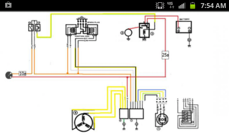
i went and made up a 'rough' sketch. every drawing ive used has a different method of displaying the basic circuit but maybe someone can tell me if im close..
i tried to use as much of this drawing here
http://www.keepandshare.com/doc/4359880/550-schematic-reva-ppt-624k?da=y
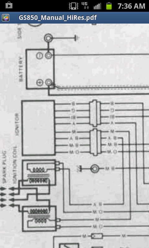
but i ended up using the high resolution drawing for the gs850gl. the wire colouring was much more accurate for what i have.. compared to the 550 schematic.
here i attempt to create a basic ignition and charge circuit.. maybe not ideally organised but tell me what im missing if anything. zoom in on link.. done it on paint :/
bike is an 82 gs850g model
note: BLUE, YELLOW, GREEN, and BLACK lead on my ignitor to the SIGNAL GENERATOR,, doesnt compare to the 550 ignitor or signal generator diagram shown in link
note: all grounds or framed earths to be used as pictured
attached file:
Not sure where you are heading with this, but in the 550 schematic I showed all connectors and the fuse box and the modifications for a single point ground.
Unless you plan to omit all of those things, it would be worth including. Also from what i know Suzuki was pretty consistent on the GS's in continuing the same color codes although there appeared to be different teams working on the electrical system of different bikes. At least they mandated consistent colors so I'm not sure what is different between a 550 and an 850. Those colors you show to the ignitor don't appear to be stock.
My original file is PowerPoint so it should be easy to modify.