Required reading for all forum users!!!
Welcome!
Register to access the full functionality of the GSResources forum. Until you register and activate your account you will not have full forum access, nor will you be able to post or reply to messages.
A note to new registrants...
All new forum registrations must be activated via email before you have full access to the forum.
A Special Note about Email accounts!
DO NOT SIGN UP USING hotmail, outlook, gmx, sbcglobal, att, bellsouth or email.com. They delete our forum signup emails.
A note to old forum members...
I receive numerous requests from people who can no longer log in because their accounts were deleted. As mentioned in the forum FAQ, user accounts are deleted if you haven't logged in for the past 6 months. If you can't log in, then create a new forum account. If you don't get an error message, then check your email account for an activation message. If you get a message stating that the email address is already in use, then your account still exists so follow the instructions in the forum FAQ for resetting your password.
Have you forgotten your password or have a new email address? Then read the forum FAQ for details on how to reset it.
Any email requests for "can't log in anymore" problems or "lost my password" problems will be deleted. Read the forum FAQ and follow the instructions there - that's what we have one for...


")

") looks good!
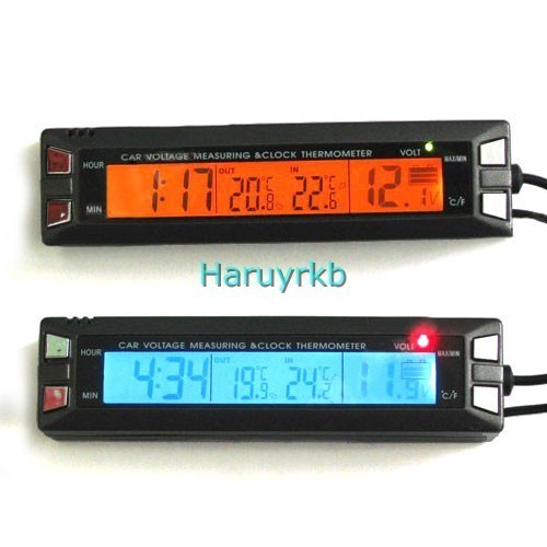
looks good! with the key on. Fully charged battery 12v+ . Maybe I need a relay for my headlight. Connected it direct to the + batt and ran it and the readout was steady. Ended up using the coil+ wire to sense from, shows 1.5-2.0v droop. Ran the wires on top of the top frame tube away from HT leads or coils as much as possible. The readout is better, more useful, just doesnt show full bat+ voltage, might change the + to the wire coming off the relay headed to the coil. Moving the wires around near the coils made the readout go major crazy, had to experiment with routing them with the least interference.