• Required reading for all forum users!!!

    Welcome!
    Register to access the full functionality of the GSResources forum. Until you register and activate your account you will not have full forum access, nor will you be able to post or reply to messages.

    A note to new registrants...
    All new forum registrations must be activated via email before you have full access to the forum.

    A Special Note about Email accounts!
    DO NOT SIGN UP USING hotmail, outlook, gmx, sbcglobal, att, bellsouth or email.com. They delete our forum signup emails.

    A note to old forum members...
    I receive numerous requests from people who can no longer log in because their accounts were deleted. As mentioned in the forum FAQ, user accounts are deleted if you haven't logged in for the past 6 months. If you can't log in, then create a new forum account. If you don't get an error message, then check your email account for an activation message. If you get a message stating that the email address is already in use, then your account still exists so follow the instructions in the forum FAQ for resetting your password.

    Have you forgotten your password or have a new email address? Then read the forum FAQ for details on how to reset it.

    Any email requests for "can't log in anymore" problems or "lost my password" problems will be deleted. Read the forum FAQ and follow the instructions there - that's what we have one for...

  • Returning Visitors

    If you are a returning visitor who never received your confirmation email, then odds are your email provider is blockinig emails from our server. The only thing that can be done to get around this is you will have to try creating another forum account using an email address from another domain.

    If you are a returning visitor to the forum and can't log in using your old forum name and password but used to be able to then chances are your account is deleted. Purges of the databases are done regularly. You will have to create a new forum account and you should be all set.

LED gear indicator. Confirm my diagram, please?

  • Thread starter Thread starter CrawlingForward
  • Start date Start date
C

CrawlingForward

Guest
I'm trying my hand at designing LED circuits and I could use some input.
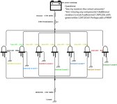
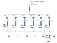
Basically, I'm planning on making a dual-brightness LED gear indicator for my GS450
When I shift to a specific gear, it switches the ground of the corresponding LED (same way the stock gear indicator works). The part that makes it more complicated is that I would like the rest of the LEDs to be dimly lit as well whenever the bike is on.
I've added a potentiometer so I can see it during the day, but it's not distractingly bright when night riding.
So does my diagram look correct?
Are my resistors correct? Should there be additional resistors on the white/green LEDs to make them match the red/yellow ones?
Is there a totally different way to design this that would be better?

Thanks,
Geoff


Attachments

  • Motorcycle Dash Circuit Diagram).jpg
    Motorcycle Dash Circuit Diagram).jpg
    85.7 KB · Views: 0
It would help if the schematic made more sense. Can't really figure out what you're connecting to what.
 
It would help if the schematic made more sense. Can't really figure out what you're connecting to what.

Sorry, I was having trouble with the program I was using.

Basically, 14v power goes through the resistor, then into the potentiometer. At that point it splits into 7 different LEDs.

Each LED's negative meets up then runs into a second resistor which then runs to ground. This is the path it takes when that gear is not selected. It should be lit, but at a lower brightness.

Each LED also has an additional path that goes to the gear selector switch and only the gear selected has ground.

So normally, each LED would be running through both resistors, making them dimly lit.

But when that gear is selected, that LED has an additional ground without the resistor, which means the selected gear's corresponding LED becomes brightly lit.

Does that makes sense?
 
It's essentially this:
GS500gearindckt.jpg
but with all the LEDs having an additional common resistor/ground.
 
I think this does what you want and is about a simple as you can make it. In a nutshell, each LED is setup with three resistors to provide a dimmable low current state. Then when you want to brighten a selected LED, the switched ground shorts out the two larger resistors on the negative side of the LED.


Each LED has 3 modes

1.) When the Ignition is OFF and O/G is not powered all LEDS are off.

2.) When the Ignition is ON and O/G has +12V then all of the LEDs will flow current depending on:
When Switched Ground is disconnected: All three resistors plus the grounded resistor (4 total)
  • 470 ohms at top
  • Individual 10K (adjust for individual LED requirements)
  • Parallel Combination:
    • Individual 10K that is shorted
    • Dimmer Pot for adjusting dim setting on all LEDS
This will allow control of each dimmable LED

3.)
When Switched Ground is connected: Current only flows through one top 470 ohm resistor.

  • 470 ohms at top
That LED will be at it's brightest but is not controllable by the Dimmer.
 

Attachments

  • LED_HI_LO_3.jpg
    LED_HI_LO_3.jpg
    37.5 KB · Views: 0
Last edited:
That drawing makes much more sense. You still may find that you'll have to play with the values on the cathode resistors and the pot a little in order to get the lighting right without it being too touchy and still be seen during the day.
 
I think this does what you want and is about a simple as you can make it. In a nutshell, each LED is setup with three resistors to provide a dimmable low current state. Then when you want to brighten a selected LED, the switched ground shorts out the two larger resistors on the negative side of the LED.


Each LED has 3 modes

1.) When the Ignition is OFF and O/G is not powered all LEDS are off.

2.) When the Ignition is ON and O/G has +12V then all of the LEDs will flow current depending on:
When Switched Ground is disconnected: All three resistors plus the grounded resistor (4 total)
  • 470 ohms at top
  • Individual 10K (adjust for individual LED requirements)
  • Parallel Combination:
    • Individual 10K that is shorted
    • Dimmer Pot for adjusting dim setting on all LEDS
This will allow control of each dimmable LED

3.)
When Switched Ground is connected: Current only flows through one top 470 ohm resistor.

  • 470 ohms at top
That LED will be at it's brightest but is not controllable by the Dimmer.

Awesome, thank you!

The explanation is super helpful as well, as I don't just want to make it, I love understanding the *why* as well.

Question, though. I would really love to be able to adjust the brightness of the selected LED as well. Would putting it at the beginning of the circuit (after the 470ohm resistor) work for that? Or would I have to find another way to configure things, like with two potentiometers or something?

I ordered a bread board and a couple assorted kits of LEDs and resistors to play with to learn and tweak, but I definitely need a bit of direction, so thank you!

(Also, what program did you use to make the diagram? Hoping to do more of this in the future)

Thanks again,
Geoff
 
Add a 5K ohm pot inline with the 470 ohm resistor and it will attenuate the "bright" setting. It will also effect the dimmed setting so you'll need to play with balancing the selected and non-selected pot levels, but it should work. You could also add in a Day/Night switch to switch the pot in/out.
 
Awesome, thank you!

The explanation is super helpful as well, as I don't just want to make it, I love understanding the *why* as well.

Question, though. I would really love to be able to adjust the brightness of the selected LED as well. Would putting it at the beginning of the circuit (after the 470ohm resistor) work for that? Or would I have to find another way to configure things, like with two potentiometers or something?

I ordered a bread board and a couple assorted kits of LEDs and resistors to play with to learn and tweak, but I definitely need a bit of direction, so thank you!

(Also, what program did you use to make the diagram? Hoping to do more of this in the future)

Thanks again,
Geoff

To adjust the brightness of the LED when bright you are going to want to range the series resistance somewhere between 470 and 2K that (to bring it way down). On the other hand the dim lights are probably starting at 2K to 5K and need to go to 10-20K to make them go out. You either control for brightness of the Brightest or the dimmest or use two pots to do it independently. The Active gear LED brightness can be controlled by putting a pot in series at the top as you shown but has to be a 0-1K or something like that.

I just drew it in Powerpoint.

You can answer most of your question with a bread board. :)

Awesome, thank you both!

I'll try and post up my results when I finish playing!
 
Ok, so after playing with the breadboard, you definitely cannot have the selected and unselected use the same potentiometer. (Which makes sense now, because you need like 200k ohms for the dim setting and only like 470 ohms for the bright setting, so they would need completely different scales of potentiometers)

So, after playing a bit, I think I've decided to have the unselected dim level constant (adjusted by resistors on each LED ground individually to balance brightness) and the bright selected level connected to the potentiometer.

I did some playing and that seems to work really well.

Thanks for the help!
 
(Oh, and for the purple LED I was experimenting with, at least, the dim setting worked well with 180k ohms and the bright setting works well with around 390 ohms plus whatever the potentiometer is set at)
 
Yeah, I saw those when I was originally searching, but decided that

a) The digital clock look was a little too...Night Rider for what I was hoping for

and b) Then I wouldn't have to learn something I've been meaning to learn for a while!

Thanks again for all the help. I've got the prototype dash mocked up out of plexiglass already (the final version will be stainless), so I'll trying and remember to post some pictures when I get that hooked up!
 
Woot woot! This thing is going to be awesome.

After being very proud of myself with my first multi-LED draft, I realized that I had the potentiometer downstream of where I was switching the ground, meaning it wouldn't work on the bike and it would *have* to have the potentiometer upstream of all the LEDs, otherwise I'd be channeling all the grounds back to one again.

Basically, it was my original design, just with more resistors.

Basically, it ended up being:
12v-->potentiometer-->LED(s)-->high ohm resistor-->constant ground
|--->low ohm resistor-->switched ground

It took a lot of tweaking with resistors to make all the LEDs function on the same basic voltage curve and light output, but I got it as close as I think is possible.

White 3mm: Dim-22k, Bright-2.2k
Green 5mm diffused: Dim-680, Bright-68
Yellow 3mm: Dim-3.9k, Bright-470
Red 3mm: Dim-10k, Bright-470

The green diffused one really threw me off, as it required *way* more power for the same brightness. A 3mm non-diffused LED instantly blew when I swapped it in the circuit, so if I wasn't using the 5mm diffused, it would be much more similar to the rest.

Enough description: Video!
(The video is me running a ground connection across the ground leads from each LED)
https://www.youtube.com/watch?v=OzwLYd-YUhg

 
Last edited:
Hope you don't mind alittle input on this. I have lots of experience with LED (I designed LED tail lights for transport trucks and school buses about 15 years ago)

Currently you have 1 470 ohm resistor for all 6 LED's. Thats not going to work properly. You need to have a serperate 470 ohm resistor for each LED. It comes down to voltage dividing, between the LED. The 470 Ohm is to control current, and drop most of the voltage (Vcc-0.7). That works fine for the LED that is currently selected (G5 in the example). So 25mA is going thru that part of the circuit. That part is fine. But once you turn on the other LED's its going to cause the voltage of the 470 resistor to drop, which will cause your G5 line to draw more current and fry the LED.

Depending on the LED you select, they will start emitting light around the 10mA point, and will max out around 30mA. I would recommend a 470 on the top for each (which gives you 25mA@12V,) and another 470 at the bottom of the resistor (instead of the 10K) to give you 12mA for non-selected. Then you can use the pots above the 470's ohm resistor to control all of them (between 12V, and the top of the 470's), and a pot at the bottom to control the non-selected LEDs.

Hope that makes sense, I will post a drawing later tonight when I get home from work.

Cheers,
Shawn.
 
Hey Shawn,

No, please! The more input the better. I'm in this to learn.

I couldn't tell from your post if I you had read the specs of the prototype, but I ended up putting independent resistors on each ground, which *seems* to be working (see video) with a single potentiometer.

I'll definitely try your recommendation out on the breadboard as well!

Question, though: So in the video above, everything works about how I'd like it to, but I'm only using like the top 1/4 of the pot range. If I wanted to take advantage of the full range for more granular control...could I do that by changing the potentiometer? Aka, it works with 0 ohms to 25k ohms (assuming a pot is linear. I have no idea on that front), so if I grabbed a pot that was like 25k or 30k or maybe 50k ohms, would that produce the same affect, but allow full use of the dial?
 
I understand exactly what you are triing to acomplish with the circuit, and i think its a great idea. I have not watched your video as where I work blocks youtube.

Not all pots are linear. When I get home I will watch your video. The circuit that was posted earlier (post #6), is a good basis, but put 6 470's (on the top of each LED). If you want the circuit to flow a minimum of 10mA thru each LED when the POT is at max resistance, and to allow 200mA or so when turned all the way off.

The LED's that you are using, do you have the companies spec sheet, or are they just random LED's?

Shawn.
 
DSC00632.jpg my gear position selector and neutral lights.

I bought different resistors to vary the brightness - and the different colors need different resistors to make the same them the same brightness - I first thought same resistor means same brightness. - nope and I still want to put a dimmer dial or switch for night and day -- each led gets it's own resistor, I use a negative switched signal.


you are definitely on the right track -- my notes got tossed but I fumbled it together enough to know what gear I'm in. 1st blue -- 3rd is red for burnout gear, the whole purpose was I hate hitting 5th gear twice. green is neutral.
 
Last edited:
Back
Top