• Required reading for all forum users!!!

    Welcome!
    Register to access the full functionality of the GSResources forum. Until you register and activate your account you will not have full forum access, nor will you be able to post or reply to messages.

    A note to new registrants...
    All new forum registrations must be activated via email before you have full access to the forum.

    A Special Note about Email accounts!
    DO NOT SIGN UP USING hotmail, outlook, gmx, sbcglobal, att, bellsouth or email.com. They delete our forum signup emails.

    A note to old forum members...
    I receive numerous requests from people who can no longer log in because their accounts were deleted. As mentioned in the forum FAQ, user accounts are deleted if you haven't logged in for the past 6 months. If you can't log in, then create a new forum account. If you don't get an error message, then check your email account for an activation message. If you get a message stating that the email address is already in use, then your account still exists so follow the instructions in the forum FAQ for resetting your password.

    Have you forgotten your password or have a new email address? Then read the forum FAQ for details on how to reset it.

    Any email requests for "can't log in anymore" problems or "lost my password" problems will be deleted. Read the forum FAQ and follow the instructions there - that's what we have one for...

  • Returning Visitors

    If you are a returning visitor who never received your confirmation email, then odds are your email provider is blockinig emails from our server. The only thing that can be done to get around this is you will have to try creating another forum account using an email address from another domain.

    If you are a returning visitor to the forum and can't log in using your old forum name and password but used to be able to then chances are your account is deleted. Purges of the databases are done regularly. You will have to create a new forum account and you should be all set.

No Spark either side till i release the starter button

  • Thread starter Thread starter Guest
  • Start date Start date
Disconnect the signal wires, + and - side
Apply 12vdc to the + terminal on the coil and then pull the power lead off. (tapping it with 12vdc)
The expectation is that it should spark each time I pull off the power source.
Alt
Nothing is going to happen!
Applying 12v to the Plus terminal is not going to charge up the coil as no current will flow through the coil if the ground side isn’t, um, grounded.

I’d just connect 12v to the positive side, and when you want the coil to charge up, connect a grounded wire to the ground side of the coil, and when you want the coil to throw a spark, release the ground.
 
Last edited:
sure as above per pqford:This being a 450 I expect it has two coils, one per plug, so just disconnect the leads from the coils and test each coil while attached to the bike ...take a positive to where the orange white would be and a ground wire to the other. You just need a momentary connection .. without a lot of gas fumes around ...

This'll keep the ignitor box out of the circuit. The spark plug need be really well grounded to engine and so too the battery groundstrap connected to the bike.
 
I may have missed this, but have you measured the impedance on your spark plug caps (and across the secondary of the coils). In your initial post you mentioned a yellow spark. Yellow is not a good color for a spark, that is a low energy spark. A good spark should be almost white. Under compression a weak spark does not have enough energy to ignite. The reason I mention this is because I just pulled my spark plug caps and mine are measuring between 500K and open circuit. Hope this is not redundant, but didn't see this in the thread.
 
I've returned again to this project.
Still no spark
Here' were my tests today. Note I'm including the BAT voltage at the start of each test so it's clear what it was at the time I did the test.
All lights are disconnected
Any bulbs removed
All terminals cleaned and dialectic grease applied.

Side stand Switch is Open in either position so it's bad, but it was bypassed for testing as well.

Still no spark on cranking.
No spark when releasing starter button.
Spark plugs resting on cylinder heads

First Test
Directly power coils with + and Neg connected. Using a 12vd charger direct to the + terminal
Both coils generate a good spark.

Seems the coils are doing their job.


Second test Voltage drop
12.18vdc at battery
+ Left coil 10.62 Ign On (not cranking)
9.33vdc (cranking)
11.20 at Solenoid (cranking)

So I still have a big drop here


Disconnected the ECU to check voltage at HARNESS side
Ignition ON. No cranking.

Bat voltage 12.35
Orange White 12.34
White 12.34
Black Yellow 12.34


Connected the ECU (Ign ON no cranking)
Bat Voltage. 12.09
Orange White 10.94
White 8.94
Black Yellow 9.20

Looking at the above, seems my drop is through the ECU. Which I suspect is the issue and may opt for a Dynatec mod unless someone happens to be in the Austin area to test a ECU :)

Open for other ideas of course.

Thanks
Alt
 
Last edited:
Disconnected the ECU to check voltage at HARNESS side
Ignition ON. No cranking.

Bat voltage 12.35
Orange White 12.34
White 12.34
Black Yellow 12.34

WITH THE IGNITION MODULE DISCONNECTED CURRENT WILL NOT BE FLOWING THROUGH THE PRIMARY SIDE OF THE COILS AND THUS THERE IS NO VOLTAGE DROP. THE VOLTAGE YOU ARE READING IS OPEN CIRCUIT VOLTAGE.


Connected the ECU (Ign ON no cranking)
Bat Voltage. 12.09
Orange White 10.94
White 8.94
Black Yellow 9.20

WITH THE IGNITION MODULE CONNECTED, IT IS PROVIDING A GROUND FOR THE PRIMARY SIDE OF THE IGNITION COILS AND THUS CURRENT IS FLOWING THROUGH THE COIL PRIMARYS. THE COIL PRIMARYS WILL CONSUME VOLTAGE, AS WILL THE IGNITION SWITCH, KILL SWITCH, ETC. HAVE YOU DISASSEMBLED AND CLEANED THE CONTACTS INSIDE THE IGNITION SWITCH AND THE KILL SWITCH?


Thanks
Alt
"....................
 
The disconnected test was just to get a base-line without the Module connected so I expected bat voltage and that was what I received.


For the connected test, I was trying to determine the source of the voltage drop.
The ignition and switch have been completed disassembled, cleaned and rebuilt prior to any the latest tests.
It was actually rebuilt the last time I worked (a few months ago) and my test results were the same before and after the cleaning.

Once the battery is changed, I will disconnect the switch entirely to see if there is a change.

Thanks
Alt.
 
Last edited:
Something different.
I will check more after the battery is charged.
In the headlight assembly I traced back the leads from the ignition switch
Pulled the orange and white leads apart. (done this before)
Cleaned them
Put them back together.
Now, both when I click the ignition off, or tap the starter button there is 1 spark on each click. I'm just tapping the starter button to complete the contact but the engine is turning enough to reach the spark trigger.
__**** Update.. Now no spark when tapping the starter when fully charged.*** just noting the behavior not saying it's a problem..

Still No spark when cranking over though.

Alt
 
Last edited:
Some additional tests
Signal Generator is about 353 ohms on each GW BW and BR / BW lead. Quite higher than the book

Coils
Primary was 5.3 ohm
Secondary is 22 ohm
Secondaries were not, till I cut back some old wire and put the caps back on.

Next, I will work on the Ignitor once I figure out the test.
 
Nothing is going to happen!
Applying 12v to the Plus terminal is not going to charge up the coil as no current will flow through the coil if the ground side isn’t, um, grounded.

I’d just connect 12v to the positive side, and when you want the coil to charge up, connect a grounded wire to the ground side of the coil, and when you want the coil to throw a spark, release the ground.

FYI on this comment.
I will note
Ignition on
12vdc applied to +
tap the negative and they spark Though more difficult to reproduce than I expected since I can tap a few times and it sparks maybe 1 out of 5 times

Now
Ignition OFF
12vdc connected
when I connect the - lead. each coils continuously sparks. I'm not removing the - lead. Solidly connected.

So it's a bit odd to see both sparking, but perhaps it's just arching past the Primary and Secondary? Seems unusual. Again, not saying it's an issue. just seems odd.
 
Due to the very high ohms readings on both Signal leads, I've ordered a full Dyna S kit that per the manufacturer, can be used on a 450 with a 1/8" spacer.
 
Dyna S kit wont fit and work on this bike. At least not without some more interesting mods as it's designed for a factory mechanical timer.

I close to throwing in the towel on this project though.

My last testing and voltage drop test were
Measuring the voltage on the orange / white coil leads.

1) only hook up the min to have spark and cranking.(starter disconnect and ignition switch and Kill switch
2) disconnect ignitor to and coil + and - to get volt reading when ignition is on. >> .This gives me a .10 volt drop. so 13.50 drops to 13.40vdc.
3) connect the + and - to the coils and recheck >>> Same voltage reading as 2 13.40
4) connect the ignitor +2volts drop without cranking. 11.40+
5) crank the starter Another +1.5 to 2v drop. 9.50 - 10.00 vdc.


Next
I disconnected the + and - from the coils and left the ignitor connected >> 13.40 vdc
Connected O/W to one of the coils leaving the - disconnected. >>> 13.40
Connected the W - lead from the coil >>> +2vdc drop
Disconnected W lead and connected B/Y - lead >>> +2vdc drop.

Tested the other coil isolated and had the same results measuring at the O/W wire on the coil

Also measuring the W or B/Y wire when either coil is connected, the drop is another 1+ volts


I would say something in the ignitor circuit, but voltage is okay till the either coil + and - connected.
There is a drop in the coil. I would expect this, but not sure how much.

Also measured the B / Y and W wires coming out of the ignitor to the - side of the coil. Same Low voltage when + and - wires are connected to either coil.
 
".......................


I’LL TAKE A CRACK AT THIS.
I’LL USE ALL CAPS SO MY RESPONSES WILL STAND OUT.

My last testing and voltage drop test were
Measuring the voltage on the orange / white coil leads.
I SUSPECT YOU HAVE THE PLUS LEAD OF YOUR DMM ON THE O/W WIRE AND THE NEG LEAD OF THE METER ON GROUND.
(THAT WILL NOT MEASURE VOLTAGE DROP IN THE COIL FEED CIRCUIT.)

1) only hook up the min to have spark and cranking.(starter disconnect and ignition switch and Kill switch
2) disconnect ignitor to and coil + and - to get volt reading when ignition is on. >> .This gives me a .10 volt drop. so 13.50 drops to 13.40vdc.
A VOLTAGE DROP OCCURS ONLY WHEN THE CIRCUIT BEING TESTED HAS CURRENT FLOWING THROUGH IT.
IF YOU HAVE DISCONNECTED THE COIL PLUS AND NEG HOW IS CURRENT FLOWING THROUGH THE O/W WIRE?
SO YOUR METER WILL READ WHAT IS REFERRED TO “OPEN CIRCUIT VOLTAGE”.
(YOU WOULD GET THE SAME READING IF YOU MOVED THE PLUS METER LEAD BACK TO THE BATTERY POSITIVE POST.)
3) connect the + and - to the coils and recheck >>> Same voltage reading as 2 13.40
AGAIN, IF THE O/W WIRE IS NOT FLOWING CURRENT, THERE IS NO VOLTAGE DROP IN THE O/W WIRE.
4) connect the ignitor +2volts drop without cranking. 11.40+
OKAY, NOW THE O/W WIRE IS NOW FLOWING CURRENT BECAUSE THE IGNITOR IS PULLING THE CIRCUIT TO GROUND AND YOU ARE SEEING A VOLTAGE DROP IN THE O/W CIRCUIT.
5) crank the starter Another +1.5 to 2v drop. 9.50 - 10.00 vdc.
PART OF WHAT YOU ARE CALLING A VOLTAGE DROP IS BECAUSE THE BATTERY CAN’T MAINTAIN A FULL 12.6V WHILE POWERING EVERYTHING AT ONCE.

THE WAY TO MEASURE VOLTAGE DROP IN THE COIL PLUS CIRCUIT IS TO PUT THE POSITIVE MEATER LEAD ON THE POSITIVE BATTERY POST AND THE NEGATIVE LEAD OF THE METER ON THE COIL + TERMINAL.

NEXT POWER UP THE COIL CIRCUIT SO THE O/W CIRCUIT IS FLOWING CURRENT. ANY CURRENT THAT CAN’T FLOW THROUGH THE O/W BECAUSE OF RESISTANCE (CORROSION, OR WHATEVER) WILL FLOW THROUGH THE METER AND BE READ AS VOLTAGE DROP. IT WILL REFLECT ANY RESISTANCE BETWEEN THE BATTERY POSITIVE POST AND THE POSITIVE BATTERY CLAMP, BETWEEN THE CLAM AND THE POSITIVE BATTERY CABLE, RESISTANCE IN THE POSITIVE BATTERY CABLE BETWEEN THE BATTERY END OF THE CABLE AND WHERE IT IS CONNECTED, AND SO ON, AND SO ON, THROUGH THE IGNITION SWITCH, ETC., ETC.

YOU COULD THEN MOVE THE POSITIVE METER LEAD FROM THE POSITIVE BATTERY POST UP TO THE IGNITION FUSE AND MEASURE THE VOLTAGE DROP BETWEEN THAT POINT AND THE COIL PLUS TERMINAL, TO PIN POINT WHERE THE DROP IS OCCURRING.


Next
I disconnected the + and - from the coils and left the ignitor connected >> 13.40 vdc
Connected O/W to one of the coils leaving the - disconnected. >>> 13.40
Connected the W - lead from the coil >>> +2vdc drop
Disconnected W lead and connected B/Y - lead >>> +2vdc drop.

Tested the other coil isolated and had the same results measuring at the O/W wire on the coil

Also measuring the W or B/Y wire when either coil is connected, the drop is another 1+ volts


I would say something in the ignitor circuit, but voltage is okay till the either coil + and - connected.
There is a drop in the coil. I would expect this, but not sure how much
 
It really should be simpler than all this...your battery seems ok per voltages and as pqford says starting the bike "pulls it down" as much as it ever will be though a slight help is disconnecting an 'always on" headlamp.

Have you yet simply applied momentary voltage to each coil and see them spark? ie: disconnect the black box and touch the primary's ground wire to ground.

Dirty kill switch or key switch or connections etc ...these are the easiest and most comprehensible uses of "voltage drop" being ideally 0 and so lossless. It's also possible to take all these out of the equation with "jumpers" across them but they shouldn't need to be unless a problem is found.

By the way, aren't your "pickups" different than the normal gs450/gsx400's? they don't look like mine. if so, the correct ohm reading might be higher for yours...y...for a lark, maybe you could test their output spinning the motor when disconnected from black box...cheap meters arent great at this but if both pickups show the same...and this speaks to the principle of "things don't usually burn out in pairs" of course they can, but usually "both bad" should redirect troubleshooting to their commonalities...things like the plate they are mounted to not being grounded or a bad battery or...

It may be your (TCI)blackbox but I would worry everything else to the max first. It so often is a simple thing...and, there are also a few tests you can try on the black box too- applying a flashlight battery to mimic the signal generators is one i remember.

the title of the thread "No Spark either side till i release the starter button" suggests that the coil is suddenly getting enough power and releasing it as a spark only when the starter is not drawing power...again, if it's not a battery "output problem" which it doesn't seem to be, then it might be a ground problem. People have had a lot of success in ignition issues grounding the plate the TCI is mounted on with a jumper to frame or even battery. A "static" VD test won't always show this and digital meters might not even running as it's a pulse. They are not great for pulses.
 
Last edited:
Hi Gorminrider.
Thanks for your reply and also to pdqford


Headlight is disconnected as is any other unused item.
Voltage drop vid has been viewed a few times. I seem to be at an issue where things go into black boxes vs just endpoint to endpoint testing thought
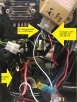
I feel like I've narrowed it down to somewhere in the coils or the b/y / w leads
Only seems to be an issue with black box connected and the coils hooked up as they should be.


Directly applying voltage to the coil is
a) with the kill switch OFF. they spark like mad when applying 12vdc direct to the coil
b) with the kill switch ON. both O/W and White (negative lead) connected to the coil. Black box disconnected, and 12vdc additionally applied to the coil + tapping the negative W, or B/Y will cause a very light spark.


Kill Switch could not be cleaner. Was thoroughly disassembled and cleaned with wire brushes, contact cleaner and dielectric greased and reassembled.


My pickups are definitely different on the GA model Hence my asking someone with a same setup test theirs for comparison as 350ohms may be okay for this flavor, but not finding it in the book for a GA.
Not using a cheapo meter on this though.
Did also test with the dyna S signal generator with an additional ground to it.
Also,
IMHO the Dyna S test was an unexpected failure too.
It uses new coils, no Ignitor.
So you are basically powering their coils and using their signal generator and magnet on an armature.
I'd think even putting this test on a bench would initial some spark, which I had none on the bike.


Black box mounting screws are cleaned and making good connection to the frame.
I could try an addition clipped wire from the box to another location, but did this months ago. Still will do it again.
I've read what I could about the battery / ignitor test. >> Have not tried, but will see if this gives more info.


I do have a oscilloscope I may see if I can figure out a way to capture a pulse from the Signal Generator. but I'm a complete NOOB with it.

Thanks
Alt
 
Click image for larger version  Name:	GS450ignition.jpg Views:	0 Size:	88.3 KB ID:	1704824

(this^ seems as big as i can upload but it might be zoomable downloaded..?)
Directly applying voltage to the coil is
a) with the kill switch OFF. they spark like mad when applying 12vdc direct to the coil
b) with the kill switch ON. both O/W and White (negative lead) connected to the coil. Black box disconnected, and 12vdc additionally applied to the coil + tapping the negative W, or B/Y will cause a very light spark.
suspicious? Given that there should be no diff in these two excepting a voltage drop from "other loads" (?!) turned on by the key switch...any other loads to disconnect? Maybe testfor something unwanted-(ammeter) or have you tried shunting across the Key switch?

otherwise per black box, naturally, IT has a voltage drop in line with the coils...semi-conductorish, silicon - say at least about .065volt ...
....if you can isolate ignition circuit entirely as a whole, applying a "signal" to duplicate the sensors' (aka the penlight batteries-see bass-cliffs-the test is there I think but I have it stored too) seemingly should work.

haven't had to do it, but spinning the crank should produce something from the sensors on a volttmeter..hopefully equal on each.

I'm not sure exactly how they apply to the TCI...simply, it seems they should interfere with a signal that normally "gates" an scr or transistor to ground...ie: stopping the coil primary supply and allowing secondary collapse...
 
Last edited:
AND ONE UPDATE
The title is no longer true. Now it only sparks when I move the kill to OFF.
Been that way for a few months since I cleaned all connections


I just tried the shunt between Orange and Red at the key connector with that piece unplugged.
Kill switch ON
Crossed the Solenoid to crank the engine.

No spark / change.

Will go over more of your above later.
 
Last edited:
I did the ignitor tests per Clymers.
Using a 1.6 AA battery with good voltage.
Ignition on
Coils directly powered 12.40vdc.


1) disconnected the signal generator
2) shoved the negative up the B/W ignitor connector
3) touched Br or G/W leads with the positive.

No spark.
Now I could be doing this test incorrectly, but attached on the photos of the Clymer and my setup showing the red + line from the AA battery touching the Br terminal (I touch and release)

Also tried a line direct from the Ignitor mounting screw to the - on the battery' (auto battery)
 

Attachments

  • photo60051.jpg
    photo60051.jpg
    79.3 KB · Views: 0
Last edited:
Back
Top