• Required reading for all forum users!!!

    Welcome!
    Register to access the full functionality of the GSResources forum. Until you register and activate your account you will not have full forum access, nor will you be able to post or reply to messages.

    A note to new registrants...
    All new forum registrations must be activated via email before you have full access to the forum.

    A Special Note about Email accounts!
    DO NOT SIGN UP USING hotmail, outlook, gmx, sbcglobal, att, bellsouth or email.com. They delete our forum signup emails.

    A note to old forum members...
    I receive numerous requests from people who can no longer log in because their accounts were deleted. As mentioned in the forum FAQ, user accounts are deleted if you haven't logged in for the past 6 months. If you can't log in, then create a new forum account. If you don't get an error message, then check your email account for an activation message. If you get a message stating that the email address is already in use, then your account still exists so follow the instructions in the forum FAQ for resetting your password.

    Have you forgotten your password or have a new email address? Then read the forum FAQ for details on how to reset it.

    Any email requests for "can't log in anymore" problems or "lost my password" problems will be deleted. Read the forum FAQ and follow the instructions there - that's what we have one for...

  • Returning Visitors

    If you are a returning visitor who never received your confirmation email, then odds are your email provider is blockinig emails from our server. The only thing that can be done to get around this is you will have to try creating another forum account using an email address from another domain.

    If you are a returning visitor to the forum and can't log in using your old forum name and password but used to be able to then chances are your account is deleted. Purges of the databases are done regularly. You will have to create a new forum account and you should be all set.

Rewiring the battery, stator, R/R and grounds

hannibal

Forum Mentor
Hello,
I just purchased a 77 GS750. I should have spent another hour or two reading these forums, and I would have saved some money. The bike test drove just fine. Got the bike home in a van, and went for a spin. Bike started up and ran fine. I went to start it the next day and got nothing. Checked the battery and saw the positive cable had come off. On closer look, it melted off at the skinny part of the O ring connector. After my first ride, I noticed a bit of smoke but thought it was just steam (it was drizzling). So I'm guessing I have some serious electrical issues, most likely an over charging problem.

I found posplayr's electrical guides and started at the battery. My multimeter is toast (couldn't get a reading and it actually got hot and started to smoke) so I took the battery to autozone. Tested at 12V with no load, but the guy pointed out the liquid inside was moving more like gel. Conclusion: the battery is no good, so I ordered the same battery to replace it. Does this look good?

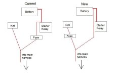
While I wait for the battery, I'm planning to rewire the stator directly to the R/R using all three wires. I'll also do the common grounding point mod either to the single bolt of the front my 8V 750 R/R (different from the 850 R/R shown in the write up), or to a spot on the frame. I haven't even seen the fuse box yet (under the tank?) but I want to figure something out for the positive side. I'll likely pause and continue posplayr's charging system check once I have the new battery and finish the grounding and stator to R/R rewiring, but before I touch the positive side.

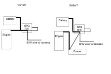
I'm comfortable with the stator to R/R wiring, but what gauge are the three wires coming out of the stator? I bought two sets of spade connectors, 16-14g and 22-18g. I also have some questions about the grounding. How big (what gauge) of wiring should I use for the common ground to negative terminal on the battery? It seems like the other grounds (from the harness, R/R, and frame if I ground to the R/R case) are the smaller gauge (same as the 3 wires from stator to R/R). Is this OK or should I go bigger? I also have a heavier gauge ground from the engine case that went directly to the battery negative terminal. Should this now go from the engine case to my common grounding point?

Two more things: the positive battery to starter relay cable (the one that fried at the battery end) is pretty heavy gauge (10g I'm guessing). Should I go even bigger with this wire or just use the same size as the common ground to battery wire that I asked about above? And lastly, the battery was grounded to the front battery box mounting bolt by a tiny wire. The front bolt goes through a rubber washer and this battery ground (and two other grounds, one from the starter relay, not sure about the other) were attached between the bolt head and the rubber washer. Is this how it came from the factory?? No wonder it has grounding issues!

I also want to say thanks for such a great forum. There is so much info here. I was kicking myself for paying for a bike that was supposed to be "ready to ride" but turned out to have these electrical issues. But with the info here, I'm confident I can update the wiring, then diagnose my charging system and get this thing running. Any harm to the bike to kick start it and ride it without a battery attached to the wiring? Can't wait to get this thing on the road...

Thanks!
 
Yup, came from factory grounded like that. I can answer a few of your questions: I like fat grounds so I usually use a slightly larger wire. Your bike likely doesn't have a fuse box, just a single inline fuse between the R/R and battery. You are right to relocate the grounds. I highly encourage you getting the wire schematics for your bike and studying it hard. Stator goes to r/r, r/r goes to bike and battery. A couple new grounds and you are headed in the right direction. You do, however, have quite a bit more elbow grease you are going to have to rub on that bike before you have a truly dependable machine. 2 main points to attack, fuel system and electrical system. Replacing all connections on the bike is also not a bad idea.
 
Oh, don't run the bike until you get that wiring figured out. Battery or not, when you fire that baby up those wires go live
 
"Any harm to the bike to kick start it and ride it without a battery attached to the wiring? Can't wait to get this thing on the road..."

leave your tired battery in, or disconnect stator from rectifier and regulator. Otherwise your regulator will not be happy!
 
I look at that main fuse, the previous owner might have put a in bigger one in or just hotwired it in some Fashion!
Mine turned out to be too low voltage and I kept popping it until I figured out it was incorrect size!
 
When I make the SPG harness for the SSPB, I crimp together 3 wires in a single oversize (10-12 AWG) ring lug; one 14 AWG and two 16 SWG. You end up with

all wires are collected to the SPG crimped and soldered.

The R/R(-) to SPG should be 14 AWG with and the open end soldered directly to the R/R (unless you have a final connector for the SH-775).
The Battery ground has a ring lug on it and is 16 AWG.
The Frame ground has a ring lug on it and is also 16 AWG.

You could make them all 14 AWG but that makes the SPG crimp a little harder.

The final ground is a B/W ring lug from the harness. I just stack it on top of the SPG with a little dielectric grease. This ground has nothing to do with charging so it is OK to just stack it and not try and tie it into the same 3 way crimp.

And as mentioned do not run the bike without a battery, the R/R will connect your electrical to rectified AC which can go upwards of 30-50 V depending upon load and RPM.
 
The man himself! Follow what posplayr says and you can't go wrong. That's what I did and now I have 2 REALLY great bikes that are as dependable as the day they were built! Btw posplayr, Thanks a million for being incredibly helpful
 
The man himself! Follow what posplayr says and you can't go wrong. That's what I did and now I have 2 REALLY great bikes that are as dependable as the day they were built! Btw posplayr, Thanks a million for being incredibly helpful


Thanks for the props :)
 
Thank you for the replies, and thanks to Jim for his write ups and help.

Made some good progress this weekend. I replaced the connectors on the 3 wires between the stator and R/R and taped off the old wires to the headlight switch. Made new battery and frame ground wires and merged these in a big ring lug. I stacked the big ring lug with the R/R ground on the single R/R mounting bolt. The R/R ground wire is quite short and I didn't want to cut off the existing ring lug to merge it with the battery and frame grounds. The wires are sealed into the unit so I'm not sure the cleanest way to extend it. I think I'll leave it like this to begin testing the charging system. If I need to replace the R/R, I'll redo the SPG. My mounting bolt was too short to add in the ring lug on the B/W harness ground so this is grounded higher up on the battery box. I correct this as soon as I find a bolt.

Question: In my earlier post, I used the term "engine case ground" to refer to the heavy gauge wire from above the transmission to the battery. Can this serve as my frame ground? This is the "frame ground" I merged with the battery ground at the SPG.

I've been studying the wiring diagram and took a look at the positive side on my bike. Current on the left, planned on the right:
attachment.php


I couldn't see where the two red wires from the R/R and starter relay intersect, but I found continuity between the wires. The fuse is a glass type (didn't read the size) covered in a plastic case. At some point, a fuse melted a hole in the case. I mentioned earlier that the positive cable on the battery had melted off. The other end on the starter relay seems to have been 95% melted as it broke off at the ring lug as I poked around. The factory wiring diagram shows the fuse on the R/R leg, not the battery side. I just looked at the wiring diagram in Jim's GS Charging System Health pdf. It shows a 15A fuse on the battery leg. Can I ask why you would fuse the battery side but not the R/R side?

I'm planning to pick up a new style inline fuse holder and charge the battery for the first time. Aside from straightening out the new fuse, I don't think I'll touch the positive side until I go through the charging system checks.
 

Attachments

  • positive wiring.jpg
    positive wiring.jpg
    33.4 KB · Views: 0
Thank you for the replies, and thanks to Jim for his write ups and help.

Made some good progress this weekend. I replaced the connectors on the 3 wires between the stator and R/R and taped off the old wires to the headlight switch. Made new battery and frame ground wires and merged these in a big ring lug. I stacked the big ring lug with the R/R ground on the single R/R mounting bolt. The R/R ground wire is quite short and I didn't want to cut off the existing ring lug to merge it with the battery and frame grounds. The wires are sealed into the unit so I'm not sure the cleanest way to extend it. I think I'll leave it like this to begin testing the charging system. If I need to replace the R/R, I'll redo the SPG. My mounting bolt was too short to add in the ring lug on the B/W harness ground so this is grounded higher up on the battery box. I correct this as soon as I find a bolt.

Question: In my earlier post, I used the term "engine case ground" to refer to the heavy gauge wire from above the transmission to the battery. Can this serve as my frame ground? This is the "frame ground" I merged with the battery ground at the SPG.

I've been studying the wiring diagram and took a look at the positive side on my bike. Current on the left, planned on the right:
attachment.php


I couldn't see where the two red wires from the R/R and starter relay intersect, but I found continuity between the wires. The fuse is a glass type (didn't read the size) covered in a plastic case. At some point, a fuse melted a hole in the case. I mentioned earlier that the positive cable on the battery had melted off. The other end on the starter relay seems to have been 95% melted as it broke off at the ring lug as I poked around. The factory wiring diagram shows the fuse on the R/R leg, not the battery side. I just looked at the wiring diagram in Jim's GS Charging System Health pdf. It shows a 15A fuse on the battery leg. Can I ask why you would fuse the battery side but not the R/R side?

I'm planning to pick up a new style inline fuse holder and charge the battery for the first time. Aside from straightening out the new fuse, I don't think I'll touch the positive side until I go through the charging system checks.

Using the engine as the frame ground is probably not going to hurt anything but I wouldn't do it. If the currents in the engine are trying to get back to the SPG before returning to the R/R(-) the most likely path of least resistance is for those engine currents to go past the battery on that big 6 awg cable. So lets say you have a Dyna S and it ground through the engine you now have those 3 amps running past the battery to get back to the SPG. Battery charging currents do not really exceed 4 amps so with the Dyna-S current wired this way you now have the voltage drop of 7 amps between the battery and SPG where if you went to the frame you would likely pick that 3 amps up and not route it past the battery. The less current going from battery(-) to the SPG the better the charging. When is good enough? You are trying to keep your voltage drops low. I like less than 0.1V but the limit in the stator pages is 0.25V. What ever it is it is reducing your 14.5V regulator setpoint by whatever the drops are at the battery reducing the charging. So in effect you are violating the SPG when you do it by sharing frame currents with battery currents before they get to the SPG.

The battery has to be fused because if it shorts you will melt wires. The most likely way to blow the main fuse is a shorted R/R. The R/R can only output 20 amps at most so it doesn't need to be fused before the individual fused circuits.
 
Thanks Jim. I think I understand your explanation about the engine ground. Are you saying the ground from the ignition (through the engine case) would want to travel back to the battery through the big wires instead of going through the smaller R/R negative wire? If this is the case, I will ground the engine case to the frame (I'm using a 9AWG wire), and run a smaller (14AWG) wire from the SPG to the same spot on the frame. Does this look better?
attachment.php


As for the fuse on the positive side, the 8V GS750 only has the single fuse (from what the wiring diagram says). I haven't seen a fuse box like on the GS850. I was thinking it would be best to fuse the R/R side because that's where all the power comes from when the bike is running. But you're saying to put it on the battery side to protect the system from the battery. Would you still recommend this without a fuse box after the ignition switch? Ideally, I'd like to add a fuse box and separate circuits in the future, but this will likely be months away. I don't even know how I will accomplish this.

Thanks again for your help. I should be able to pick up my new battery today. Add a day to charge and I'm hoping to start it up tomorrow.
 

Attachments

  • grounds.jpg
    grounds.jpg
    46.9 KB · Views: 0
I can't seem to edit my post so I'll an this FYI: the engine ground cable originally ran from the engine case to the negative terminal on the battery, which sounds like the worse thing to do!

Also, using the 9AWG wire because that's all I had. I ordered some 14 AWG wire just in case...
 
A couple of quick comments:
The engine is bolted to the frame is various places. Except for dirt and grime it is going to be hard to improve upon that with a ground strap. In fact you might create a sneak path for the starter and fry something. I would NOT do it.

I assume what you have labeled as SPG R/R is in fact the R/R with a mounting bolt used for the SPG. That being the case I don't know why you need a heavy wire from the battery. That Should carry 4 amps at most if just charging and maybe 7 amps if you have a DynaS. Do you have a Dyna S?

NO MATTER what, if you short your battery it will supply many many amps melting wires. So no matter what fusebox or single fuse you have you better fuse the battery as close to the battery as is practical. There is nothing more to be said. If you want fuses in other places, fine, but if you ever have a R/R short and there is no fuse you will regret it.


This is a standard configuration with allowance for various numbers of wires from the R/R. If you realize that all current has to return to the R/R(-) , then it should be clear that the SPG is the collection point for all of those current before the final run to the R/R(-). The SPG is collecting any frame currents, B/W currents and finally the battery charging currents. The only thing to be careful of is that the battery wire only carries charging currents, however in practice this might be hard to do when there is a large 6 -8 AWG starter grounding strap to the back of the engine.
Generally the ignitor does not ground out to the engine, but the Dyn S does. There is probably nothing you can do about that it is going to return via the ground strap right past the battery and share current with battery charging currents exactly what you don't want it to do. But alas there is nothing you can do short of running a separate ground wire to the plate of the DynaS. Is it worth it? Probably not.
If you had a clamp on amp meter you could test all of this and much of the mystery would go away.

What are you doing different and why? I'll try and answer those questions .

picture.php
 
Yes, SPG R/R refers to the mounting bolt on the R/R. I stole the 9 AWG wire from an amp install kit I had lying around. After considering that the kit is designed for an amp that draws 400+W (almost 35A), I realized the massive wire is indeed overkill. I do not have a Dyna S and would likely only install one if I have ignition issues down the road. I didn't think this would be harmful to the system though. On your recommendation, I will replace the battery to SPG ground with 14AWG wire. I'll also add a 14AWG frame to SPG wire. Is it safe to toss out the engine grounding strap completely? Or should I just run a smaller 14 AWG from engine to frame?

I had a brain fart on the fuse location. If I learned anything from installing an amp or two, it's that the fuse goes as close to the battery as possible.

My thoughts on the engine grounding strap was that it would ground the ignition back to the SPG. Didn't know the OEM ignitor doesn't ground to the engine case. I'm not trying to do anything differently, only complete the SPG mod, make sure the main fuse is correctly wired, and continue thinking about the positive side wiring. The more I think about it, the more I realize I need to create separate fused circuits. So my game plan is to 1) change the battery ground to 14AWG and add a frame to SPG ground, 2) make a 14AWG engine to frame ground if you suggest doing so, 3) install newer blade type fuse holder (near the battery!), 3) correctly charge the new battery, and 4) begin the charging system checks you've documented so well. My final step will be to start at the front of the bike, check and clean all switches and terminal, and create new separately fused circuits.

Question about the diagram above. The BR wire coming off the ignition should go straight to the fuse box without a connection to the R/R again right? And what size fuse should I use on the main fuse (#5)? I've seen 20A and 30A. Is this as simple as adding all the current draws in the system and adding a safety factor (eg. total load=25A so go with a 30A main fuse)?

Not trying to reinvent the wheel!
 
Comments inserted below

Yes, SPG R/R refers to the mounting bolt on the R/R. I stole the 9 AWG wire from an amp install kit I had lying around. After considering that the kit is designed for an amp that draws 400+W (almost 35A), I realized the massive wire is indeed overkill. I do not have a Dyna S and would likely only install one if I have ignition issues down the road. I didn't think this would be harmful to the system though. On your recommendation, I will replace the battery to SPG ground with 14AWG wire. I'll also add a 14AWG frame to SPG wire. Is it safe to toss out the engine grounding strap completely? Or should I just run a smaller 14 AWG from engine to frame?

For the SSPB I make a little SPG harness like in the picture below. I bring together a battery, frame and R/R(-) ground wire into a single ring lug. As I recall, I can just get a 14 awg for the R/R(-) along with 16 awg for the other two wires all to fit inside of a 10-12 AWG crimp. The 10-12 AWG ring lug then becomes the SPG and it can be put anywhere even floating. The frame and battery wires have 6mm ring lugs (16 awg wires) and the final 14 awg is soldered into whatever is coming out of the R/R(-). For a compufire I put a ring lug on it and screw it into the case as that is how they are grounded. When you bolt down the SPG I just stack my B/W ring lug from the harness on top. You can make stuff bigger but based on my calculations and going no more tha n1 ft length on any of these you will have low voltage drops. Crimp and sparingly solder all ends.

There is a summary of calculations here; they are for the SSPB but that grounds would apply to your case if you follow the SPG guidelines.

http://www.thegsresources.com/_foru...x-STANDARD-INSTALLATION&p=1965992#post1965992

attachment.php


I had a brain fart on the fuse location. If I learned anything from installing an amp or two, it's that the fuse goes as close to the battery as possible.

Yes

My thoughts on the engine grounding strap was that it would ground the ignition back to the SPG.

We are really "gilding the lily". For the amount of potential benefit, I would be much more concerned with giving the potential for giving the starter current a new return path. So no dont do it. If you were really worried about it and you did a Dyna S ,it would be better to run a ground direct from the Dyna S back to the SPG rather than trying to modify the frame to engine current flow. Unless someone throws an accessory on or does the Dyna S most all other return currents run through the B/W. That was part of the issue and why adding the extra battery strap ground relieves the B/W and makes the R/R and battery tied closer together. The Frame ground is just an "in case someone" adds more accessories with frame ground returns.

Didn't know the OEM ignitor doesn't ground to the engine case. I'm not trying to do anything differently, only complete the SPG mod, make sure the main fuse is correctly wired, and continue thinking about the positive side wiring. The more I think about it, the more I realize I need to create separate fused circuits.

Separate 10 amp circuits is a very good idea

So my game plan is to 1) change the battery ground to 14AWG and add a frame to SPG ground, 2) make a 14AWG engine to frame ground if you suggest doing so, 3) install newer blade type fuse holder (near the battery!), 3) correctly charge the new battery, and 4) begin the charging system checks you've documented so well. My final step will be to start at the front of the bike, check and clean all switches and terminal, and create new separately fused circuits.

Good, but don't do 2.)

Question about the diagram above. The BR wire coming off the ignition should go straight to the fuse box without a connection to the R/R again right? And what size fuse should I use on the main fuse (#5)? I've seen 20A and 30A. Is this as simple as adding all the current draws in the system and adding a safety factor (eg. total load=25A so go with a 30A main fuse)?

The BR is for R/R's with sense wires. If you use the SH-775 you can ignore it. The Honda is the only one I would even consider that has the sense wire.

You only need a 15 amp main fuse for the battery.

Not trying to reinvent the wheel!
 

Attachments

  • SPG_Harness.jpg
    SPG_Harness.jpg
    8.7 KB · Views: 0
Thanks for the reply and the link. I now understand why the R/R ground should be the largest wire at the SPG. I've ordered 16AWG wire for my battery and frame ground. Again, still hesitant to cut the ring lug off my short R/R ground so i'll stack the battery/frame grounds, then the R/R ground, and then the B/W ground with dielectric grease in between.

Time has provided more clarity and I've concluded that if I must do this, I have to do it right. I'm using crimp on terminals but I plant o solder and shrink warp the terminals. What's the correct way to make these connections? Should I crimp, solder, and wrap, or solder the bare wire, crimp, then wrap?

Thanks for the clarification on the R/R sense wire. My goal is to rewire with the OEM equipment to get to a functional state. Then I can perform the tests and tackle whatever's bad. If I need a new R/R, my current choice would be the SH-775 and I would definitely integrate the R/R negative with the battery/frame ground ring lug. I've had to pause to order some tools and supplies so I'll spend the rest of the week thinking about how to fuse the positive side. I'm looking at how Suzuki did the 3 circuit set up in the later bikes. I'm pretty sure this will require me to open up most of the existing harness. And I'm really scared of the wiring on the handlebars. I unscrewed them switches to look inside and they were full of cobwebs and random debris. Hoping I can clean them without breaking any connections. But i guess that's what a soldering iron is for.

Thanks again!
 
What's the correct way to make these connections? Should I crimp, solder, and wrap, or solder the bare wire, crimp, then wrap?
If you must crimp AND solder, then crimp first, and be careful the solder doesn't wick up the strands, else vibration will just crack it later.
If you solder first, the solder will creep out from under the crimp later on, leaving a slack and heating-up connection.
 
If you must crimp AND solder, then crimp first, and be careful the solder doesn't wick up the strands, else vibration will just crack it later.
If you solder first, the solder will creep out from under the crimp later on, leaving a slack and heating-up connection.


Never occurred to me to solder then crimp LOL. but yes be very sparing with the solder. I use a little clip on the insulation crimp to pull away heat and help keep the solder from wicking up the wire as much as it pulls heat creating a heat dam. I leave some extra length on the conductor so it extends further out onto the ring lug or spade. Heat the connector there and flow just enough to insure good electrical contact. Use flux if the wire is dirty.

I guess pictures would be good, but the only examples I have at the moment are of very small molex pins.
 
Back
Top