• Required reading for all forum users!!!

    Welcome!
    Register to access the full functionality of the GSResources forum. Until you register and activate your account you will not have full forum access, nor will you be able to post or reply to messages.

    A note to new registrants...
    All new forum registrations must be activated via email before you have full access to the forum.

    A Special Note about Email accounts!
    DO NOT SIGN UP USING hotmail, outlook, gmx, sbcglobal, att, bellsouth or email.com. They delete our forum signup emails.

    A note to old forum members...
    I receive numerous requests from people who can no longer log in because their accounts were deleted. As mentioned in the forum FAQ, user accounts are deleted if you haven't logged in for the past 6 months. If you can't log in, then create a new forum account. If you don't get an error message, then check your email account for an activation message. If you get a message stating that the email address is already in use, then your account still exists so follow the instructions in the forum FAQ for resetting your password.

    Have you forgotten your password or have a new email address? Then read the forum FAQ for details on how to reset it.

    Any email requests for "can't log in anymore" problems or "lost my password" problems will be deleted. Read the forum FAQ and follow the instructions there - that's what we have one for...

  • Returning Visitors

    If you are a returning visitor who never received your confirmation email, then odds are your email provider is blockinig emails from our server. The only thing that can be done to get around this is you will have to try creating another forum account using an email address from another domain.

    If you are a returning visitor to the forum and can't log in using your old forum name and password but used to be able to then chances are your account is deleted. Purges of the databases are done regularly. You will have to create a new forum account and you should be all set.

Rewiring the battery, stator, R/R and grounds

I'm looking at how Suzuki did the 3 circuit set up in the later bikes. I'm pretty sure this will require me to open up most of the existing harness. And I'm really scared of the wiring on the handlebars. I unscrewed them switches to look inside and they were full of cobwebs and random debris. Hoping I can clean them without breaking any connections. But i guess that's what a soldering iron is for.

Thanks again!

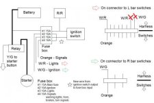
If you look here you will see how to take a 550 and separate out the circuits. It is really not too bad. This is standard install for a non fuse box biek where the SSPB is installed.

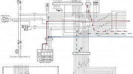
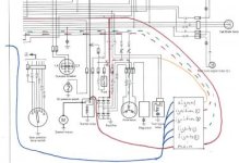
This is a preliminary markup of a 1977 GS550 schematic and represents what is involved with converting your single fuse bike to use the SSPB.
SSPB Install for 1977 GS550


Is the other link doesn't work try this one.
http://www.keepandshare.com/doc/6791183/sspb-install-1977-gs550-pdf-1-0-meg?da=y
 
Link requires login. I tried right click, save as. I'm pretty sure I've clicked on that link over in your SSPB thread. Would love to see that diagram.
 
Link requires login. I tried right click, save as. I'm pretty sure I've clicked on that link over in your SSPB thread. Would love to see that diagram.
email me at solidstatepowerbox@gmail and I'll send it.
 
Just remember dialectic grease is an insulator not a conductor. Put it on terminals AFTER they are connected. Do not put on connecting surfaces.

http://www.wisegeek.org/what-is-dielectric-grease.htm


Generally the grease is displaced under normal pressure of electrical contacts. That is the reason why it is a bit of a surprise that it is non conductive. So normally you can just push it into the end of a connector and then push the connector together without issue. Have have done this plenty, in fact it would be kind of worthless if you had to apply it after making sure you have clean dry contacts. How would you ever re-attach a connector after having dialectic grate applied if you have to only apply after contact is made. You would have to fully clean then connect then reapply . This is generally never necessary.

The main problem I see with it is you will have difficulty getting into crimps (where as DeOxit will flow very well), so DG would best be used on battery terminals and large flat ring lugs or perhaps inside switches.
 
Just picked up some deoxit. I have dielectric grease at home. I was planning to clean the switches and multi pin connectors with deoxit and replace all bullet connectors with m/f spade connectors (crimped then soldered then grease then heat shrink). Good plan?

Is deoxit more than a cleaner? Should it be left on the connector or switch?
 
Jim, where do you put your clamp to pull away heat, towards the wire side of the crimp?

On the portion of the crimp that squeezes the insulation. It help to avoid melting the insulation as well.
 
Just picked up some deoxit. I have dielectric grease at home. I was planning to clean the switches and multi pin connectors with deoxit and replace all bullet connectors with m/f spade connectors (crimped then soldered then grease then heat shrink). Good plan?

Is deoxit more than a cleaner? Should it be left on the connector or switch?

It cleans off oxidation and then protects the surface. I cleaned off my gas sensor which was subject to much more than just surface rust. After acid bath, the deoxit kept it from further rusting.


Alot of bullet connectors dont really carry any current and can be left. It it is lights or ignition, the you should probably replace. But the newer bullet connectors are much better than what came originally on the bike. Especially the multiple ground claps for bullets are close to an accident waiting to happen..

What I have been doing with full block connectors (not just single bullets or spades) is I pull a small length of Harbor freight shrink tubing (3/4" or 1" it is pretty cheap but good quality) over the connector, apply the dielectric grease after cleaning, then connect the connector and pull a zip tie around lengthwise about the connector to keep it from coming apart. On the ED some tend to come apart and I had a PO actually super glue one together that had to be destroyed to get it apart.

Anyway after all that and secured with the zip tie, you can pull the shrink tubing back over the lot and heat it up. I just recently needed to pull mine apart and the connectors all still look factory new.


I just looked at HF and could not see the stuff; it comes in 4 small boxes. each for 1/4" , 1/2", 3/4" and 1" (something like that)
 
Last edited:
Quick update:
I was a bit overwhelmed so I had to slow down and take a step back. I've gotten my plan together and should have all my parts by Monday. I plan to get started this weekend with the goal of completing my electrical system overhaul by the following weekend.


I have one (hopefully) last question about the ground side. I usually see a nice black-painted battery box in others' pics. My battery box is rust colored because it's covered in rust. I can't even find continuity between two spots an inch apart. With the SPG on the R/R mounting bolt, isn't my battery box now out of the picture? Since it's no longer being asked to carry current from various grounds on the box and frame, the rust shouldn't affect my grounding right?


I opened up the headlight bucket to look around and discovered that the plastic bucket is cracked. I believe I have the smaller 6 3/8" headlight and the previous owner wedged a 7" light in there. On top of that, the sealed beam filament was loose inside the housing. As long as I can swap out the bucket without affecting my new wiring, I'll just add the headlight and bucket to the list of parts needed and sort that out after the bike is running.


So on to the positive side (of the battery). Thanks to Jim for the SSPB into GS550 diagram. It was a little confusing but I think you validated my idea of using the W/G and W/R wired (previously used to carry the 3rd leg of the stator to the headlight switch and back) to create the new 3 circuit system. The first circuit will be Ignition. This runs to the kill switch on the right bar. Second is Lights which goes to the headlight switch on the left bar. The third will be Signals, which goes to the warning lights in the gauge cluster, horn, brake switches, and turn signals.


attachment.php


Because the Signals circuit has multiple connections, this will remain on the stock orange wire. I plan to use the W/R wire for the Lights circuit and the W/G for the Ignition. At the connector/plug to the L bar switches, I'll de-pin the W/G, W/R, and orange wires. The W/R wire will now run to the pin where orange used to go. This completes the Lights circuit. I then will run the W/G wire to the connector for the R bar switches. Again, I'll de-pin the orange wire and replace it with the W/G wire. This completes the Ignition circuit. I may switch the W/G and W/R wires if one is better suited to move from its stock connection at the headlight switch to its new home on the kill switch. Finally, with the orange wire (that formerly carried current everywhere) now removed and capped off from the L and R switches, it will serve as my Signals circuit.


The Ignition circuit grounds through the coil and/or spark plugs and the contact breaker (this is just a distributor used to time the ignition right?). So this circuit will be grounded to the SPG through the frame grounding wire. The Lights circuit grounds exclusively through the B/W wire, again accounted for in the SPG. Lastly, the Signals circuit grounds through the gear position switch (engine case), oil pressure switch (engine), and the B/W. All set on the grounds.

Any comments or questions about this plan?


I didn't think I'd need anything else, but after drawing it out, I will need a brand new wire to deliver current from the ignition switch to the new fuse box. I begin cleaning the connections. I started at the starter relay because it was easy to pull off. Hit it with some deoxit and a toothbrush, and it cleaned up really nicely. Resistance across the trigger and ground fell from about 4 ohms to 3.6 (service manual says 3.5 +/- 0.5 ohms). So I'm feeling pretty good that I can get this thing cleaned up and running well. I have most of my supplies but I'm still waiting for a bike cover and battery charger from BikeBandit and a new multimeter. Gonna grab some of those little pointy toothpick/flosser things to help me clean the bullet connectors. Can't fill my battery til the charger gets here so "first" will hopefully be next week.
 

Attachments

  • positive side wiring.jpg
    positive side wiring.jpg
    18.4 KB · Views: 0
I have one (hopefully) last question about the ground side. I usually see a nice black-painted battery box in others' pics. My battery box is rust colored because it's covered in rust. I can't even find continuity between two spots an inch apart. With the SPG on the R/R mounting bolt, isn't my battery box now out of the picture? Since it's no longer being asked to carry current from various grounds on the box and frame, the rust shouldn't affect my grounding right?

You should clean it up. There is normally a Harness B/W with ring lug providing a ground for the battery box.

I opened up the headlight bucket to look around and discovered that the plastic bucket is cracked. I believe I have the smaller 6 3/8" headlight and the previous owner wedged a 7" light in there. On top of that, the sealed beam filament was loose inside the housing. As long as I can swap out the bucket without affecting my new wiring, I'll just add the headlight and bucket to the list of parts needed and sort that out after the bike is running.

I guess it depends on what you put in to replace if it needs rewiring. I would suggest a LED bulb to reduce the current loads on the harness. Recently reviewed a Cyclops 3800 but there are other 30w LED's which will do nicely.

So on to the positive side (of the battery). Thanks to Jim for the SSPB into GS550 diagram. It was a little confusing but I think you validated my idea of using the W/G and W/R wired (previously used to carry the 3rd leg of the stator to the headlight switch and back) to create the new 3 circuit system. The first circuit will be Ignition. This runs to the kill switch on the right bar. Second is Lights which goes to the headlight switch on the left bar. The third will be Signals, which goes to the warning lights in the gauge cluster, horn, brake switches, and turn signals.

The schematic I sent was with a SSPB and so you would need to treat it as a bunch of relays with required triggers that replaces the fuse box. In general all of your circuits will still be driven from the same place. You may or maynot have triggers depending upon whether you do relay mods. Coil relay is generally a good idea, and the headlamp can draw 5 amps if using an H-4 halogen.

I would suggest marking up the OEM schematic like I did. The notes are organized and numbers to 1.) add wires, 2.) add jumpers and 3.) add cuts. Only 3 wires were added by using the W/R and W/G which are freed up getting rid of the stator loop.


The Ignition circuit grounds through the coil and/or spark plugs and the contact breaker (this is just a distributor used to time the ignition right?). So this circuit will be grounded to the SPG through the frame grounding wire. The Lights circuit grounds exclusively through the B/W wire, again accounted for in the SPG. Lastly, the Signals circuit grounds through the gear position switch (engine case), oil pressure switch (engine), and the B/W. All set on the grounds.

That is a pretty good summary.
 
I did mark up a diagram as you did. I hadn't sorted out the battery to main fuse wiring yet so I didn't scan it. If I end up stopping by work this weekend, I'll definitely scan and post it. I've been through the factory diagram several times and I'm confident my mods achieve the objective. I strongly considered adding a coil relay but decided againat it. I just want the wiring to be well enough to point to any potential problems. When I started, the bike was trying to fry itself to death. Once I finish this stage of updates, I'll be able to explore the ignition system in detail. If (or when) necessary, I'll add relays where needed.

About the battery box, I have the battery, frame, R/R, and B/W grounds all stacked at the R/R mounting bolt. So technically nothing must travel through the box to reach ground. If I continue to show grounding issues, I'll remove the box and get it acid dipped or sandblasted or however you deal with a rusty epidemic.

No rain and not too hot this morning. Trying to make hay while the sun shines. Gonna find a place to mount the new fuse vox, then finish the grounds. If I can change the bucket with having to undo anything, I'll start on the positive side wiring. I probably won't have time to touch it next week, so I really need to make progress this weekend.
 
I was able to confirm I have a 7" headlight in an 8" bucket. Looking for a new metal bucket and deciding on a headlight (H4 or LED). I'm definitely going to do relays in the second phase: headlight relay, "headlight cut when the starter is engaged" relay, and an ignition coil relay. I've already gotten the diagrams drawn up, and I won't have to touch any of my new wiring to add relays down the road. But that will come after getting the bike back to "stock" condition so I can test the charging system.

Filled my new battery last night. Will get it on the charger as soon as my multimeter gets here. Hoping to have time to finish the wiring this week. I've measured and remeasured dozens of times. I just have to make that first cut!
 
When I make the SPG harness for the SSPB, I crimp together 3 wires in a single oversize (10-12 AWG) ring lug; one 14 AWG and two 16 SWG. You end up with

all wires are collected to the SPG crimped and soldered.

The R/R(-) to SPG should be 14 AWG with and the open end soldered directly to the R/R (unless you have a final connector for the SH-775).
The Battery ground has a ring lug on it and is 16 AWG.
The Frame ground has a ring lug on it and is also 16 AWG.

You could make them all 14 AWG but that makes the SPG crimp a little harder.

The final ground is a B/W ring lug from the harness. I just stack it on top of the SPG with a little dielectric grease. This ground has nothing to do with charging so it is OK to just stack it and not try and tie it into the same 3 way crimp.

And as mentioned do not run the bike without a battery, the R/R will connect your electrical to rectified AC which can go upwards of 30-50 V depending upon load and RPM.

Jim,

If the larger ring lug for the SPG harness is mounted to the frame, such as an airbox mount, is a third wire for a frame ground necessary?

I'm thinking that in this case, I only need one 14 AWG wire for the r/r and another 14 AWG wire for the battery crimped into a single ring lug. I'm not using a SSPB, so I will have a ring lug for the battery and solder the r/r wire to the connector for the SH-775.

What are your thoughts?
 
If you make the SPG a frame mount then you do not need a wire from the SPG to the frame; it would be to itself.
 
Back
Top