• Required reading for all forum users!!!

    Welcome!
    Register to access the full functionality of the GSResources forum. Until you register and activate your account you will not have full forum access, nor will you be able to post or reply to messages.

    A note to new registrants...
    All new forum registrations must be activated via email before you have full access to the forum.

    A Special Note about Email accounts!
    DO NOT SIGN UP USING hotmail, outlook, gmx, sbcglobal, att, bellsouth or email.com. They delete our forum signup emails.

    A note to old forum members...
    I receive numerous requests from people who can no longer log in because their accounts were deleted. As mentioned in the forum FAQ, user accounts are deleted if you haven't logged in for the past 6 months. If you can't log in, then create a new forum account. If you don't get an error message, then check your email account for an activation message. If you get a message stating that the email address is already in use, then your account still exists so follow the instructions in the forum FAQ for resetting your password.

    Have you forgotten your password or have a new email address? Then read the forum FAQ for details on how to reset it.

    Any email requests for "can't log in anymore" problems or "lost my password" problems will be deleted. Read the forum FAQ and follow the instructions there - that's what we have one for...

  • Returning Visitors

    If you are a returning visitor who never received your confirmation email, then odds are your email provider is blockinig emails from our server. The only thing that can be done to get around this is you will have to try creating another forum account using an email address from another domain.

    If you are a returning visitor to the forum and can't log in using your old forum name and password but used to be able to then chances are your account is deleted. Purges of the databases are done regularly. You will have to create a new forum account and you should be all set.

Simplified Wiring gs450

  • Thread starter Thread starter Deadeye008
  • Start date Start date
D

Deadeye008

Guest
Okay, new member here. Yes, I used the search already. I wish I would've found this site awhile ago though haha. Cliff's diagrams have been a big help already.

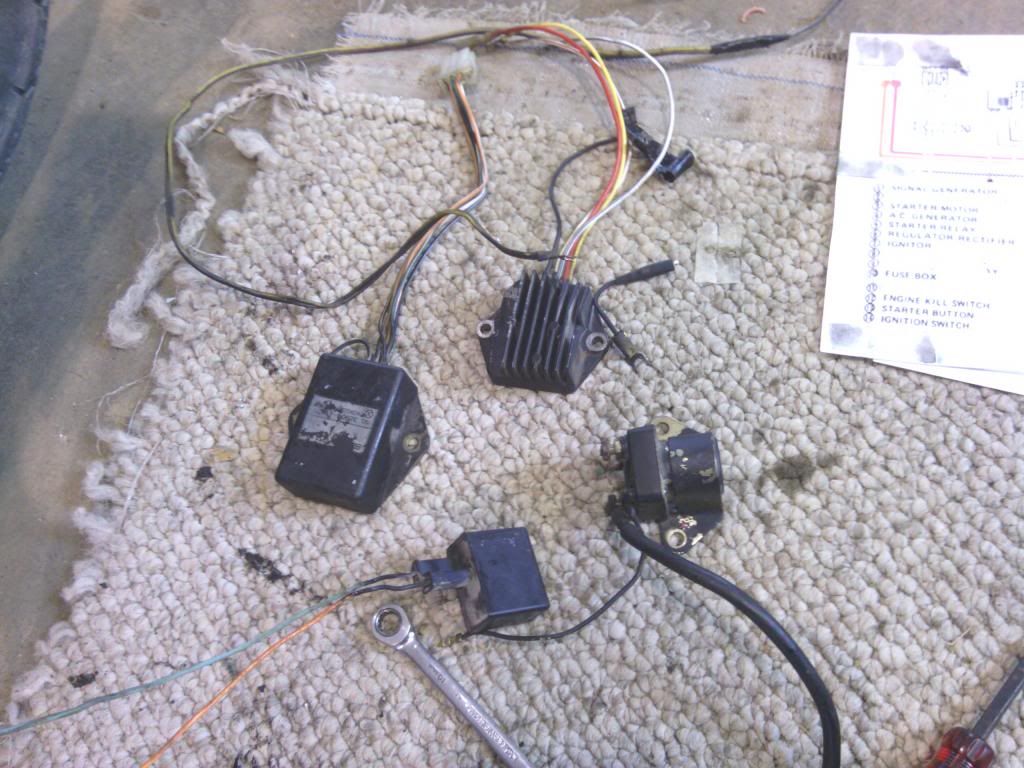
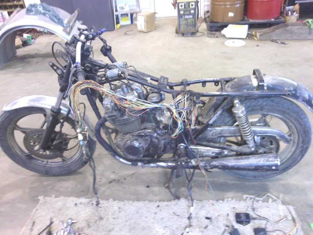
I'm building a non street legal 81gs450 :cool:. I have torn it down already and the wiring is a mess (PO..) I am not an electrical savvy guy at all. So I need some help.

Things I don't need...
-turn signals front or rear
-high/low beam switch (just high is fine)
-gear indicator
-neutral indicator
-speedo
-tach
-oil temp indicator
-off/run switch
-horn

Things I'd like to have/need...
-killswitch
-brake light ( I will be running a front brake btw)
-headlight switch
-the whole ignition system (obviously haha)
-and I'd like to attach a cigarette lighter outlet onto it somehow

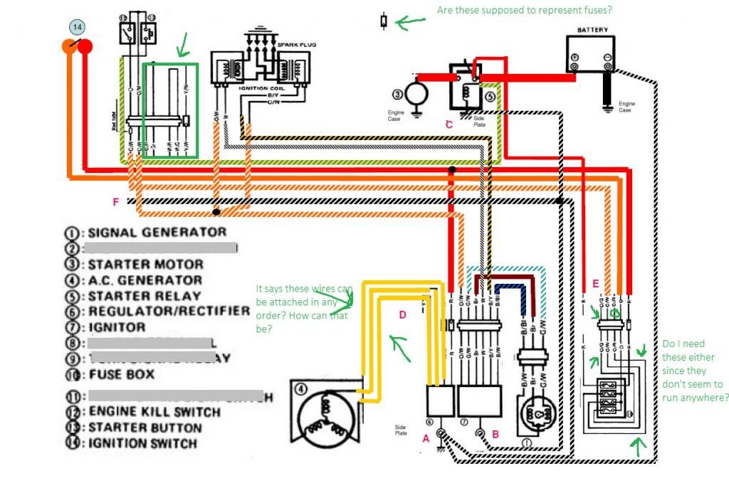
I have the wiring diagram from cliff. But guys, I'm not good at this and its real compicated for me. Is there anyway to simplify it all so that I just have whats noted up top? BTW, I have a full shop, plenty of wiring, and a voltometer.

Thanks, and I'll be sticking around, with lots of pics too :D
 
No, haven't seen that one yet. Just printed it out though. Thats a big help, thanks.
 
Why not just remove all the (supposedly) unnecessary items and leave the wiring alone?
icon_shrug.gif


There is a remote chance that you might realize that you really do need something that you removed, it will be SO much easier to re-attach it. :-\\\

.
 
That was the original plan. But once I tore into the wiring. I noticed quite a few bad wires, and like I said, it's already been touched. Which makes it harder for me to figure out what everything is for.
 
IMG_20130725_112858.jpg


The one to the left is the ignitor, the top one is the R/R. Right? So whats the bottom one? And the right one is the starter relay correct?

:o:o

IMG_20130725_112911.jpg


And if anyone was interested in seeing this hunk o' junk, here it is as she sits.
 
IMG_20130725_112858.jpg


The one to the left is the ignitor, the top one is the R/R. Right? So whats the bottom one? And the right one is the starter relay correct?

Correct on the ignitor and R/R.
icon_thumbsup.gif


Yes, the item on the right is your starter solenoid, the one at the bottom is your turn signal flasher.

.
 
So, since I'm not running turn signals. The flasher can be completely scrapped correct? Also does any body know what amp fuses should be used when using this wiring diagram? When I tore into the bike, there was only one fuse in it to begin with, and to me, it seems I need atleast two for this diagram? The one that was on the bike, I don't remember where it was attached, but it's a 20 amp.

http://www.mtsac.edu/~cliff/storage/gs/550_Schematic.pdf
This was the original^^^

Can you guys take a look at this one?
NewSchematic.jpg
 
Last edited:
OK, I'll take a shot at this one.
Upper left, area inside green box:
If you wire your stator directly to the R/R (as shown), you can scrap everything inside the box. The bar in the box is a connector, probably a 9-pin, could be under the tank or in the headlight bucket.

Moving to the right:
No, those are not fuses, they are connectors.

Moving to bottom center:
Yes, they can be connected in any order. That's because it is a 3-phase AC (alternating current) generator. The R/R is a Rectifier/Regulator which changes the AC to DC (direct current), then regulates it to the voltage required by the bike. The diodes in the R/R don't care which leg of the stator is feeding them, you can connect them in any order.

Moving to the bottom right:
The wires you have mentioned do not have to be there. Evidently whoever modified that diagram did not bother to remove them or possibly just left them so parts of the diagram would look familiar, so you could see what was changed.

.
 
Steve,
The schematic is from here. :o

http://www.thegsresources.com/_forum/showthread.php?t=153727&highlight=550+bobber+schematic

I added additional comments below.

Jim

OK, I'll take a shot at this one.

Upper left, area inside green box:
If you wire your stator directly to the R/R (as shown), you can scrap everything inside the box. The bar in the box is a connector, probably a 9-pin, could be under the tank or in the headlight bucket.

I'm just showing the original connector and those wire that needed to be retained from it. Since there are only three wires connected a three wire connector could be substituted.

Moving to the right:
No, those are not fuses, they are connectors.

Correct again showing all connections that need to be maintained as they would be in their original connector configuration. If new connectors are desired, you would be free to choose what you like after you have completed adding the lights.

Moving to bottom center:
Yes, they can be connected in any order. That's because it is a 3-phase AC (alternating current) generator. The R/R is a Rectifier/Regulator which changes the AC to DC (direct current), then regulates it to the voltage required by the bike. The diodes in the R/R don't care which leg of the stator is feeding them, you can connect them in any order.

Yes of course.

Moving to the bottom right:
The wires you have mentioned do not have to be there. Evidently whoever modified that diagram did not bother to remove them or possibly just left them so parts of the diagram would look familiar, so you could see what was changed.

In the original post I omitted all lights which are what is connected to the O/G(signal) and O/R(headlamp) circuits. That is where you would connect your lights after deciding what you are going to use.

There are no lights/blinkers included in the schematic. Obviously they should be added.
Quote:
Generally I would not run the stator leg through the handlebar switch (this is generally recommended on all GS's) but rather have the headlamp on all the time and direct connect the 3 stator wires to the R/R.


The OEM fuse box has unused circuits for things like lights.
No gages? You can add a wires for the coil (-) for the electronic tach, lights. (I left a ground in the harness running from front to back)
This could be modified easily for a Coil relay mod. This would be simple to do now. (I left it out)
There is an extra ground wire because some people may not have the starter solenoid and R/R mounted on the same plate. If you relocate igniter, solenoid, R/R to the same plate then things get simpler. Just make sure the Star grounding configuration at the R/R is maintained.
Any other accessories can be added to the extra circuits shown

.
 
Last edited:
So, since I'm not running turn signals. The flasher can be completely scrapped correct? Also does any body know what amp fuses should be used when using this wiring diagram? When I tore into the bike, there was only one fuse in it to begin with, and to me, it seems I need at least two for this diagram? The one that was on the bike, I don't remember where it was attached, but it's a 20 amp.

The standard fuses are 15 amps main (between battery and ignition switch)
and
10 amps for ignition.

Headlamp and signal loads are typically 10 amps each but depends on what lights you are using.
 
Thanks, Pos, I was just going off what was shown, did not bother to follow the link that was also provided. :o

.
 
Thanks, Pos, I was just going off what was shown, did not bother to follow the link that was also provided. :o

.

I was mostly agreeing with you as the OP had apparently not considered providing the original context for the schematic.
 
Yep, I saw all the agreement, then the additonal parts that I would have seen, if I had bothered to look at the original (which I have since done).
icon_thumbsup.gif


The letters in the diagram posted did not make much sense until viewing the original document, and it also explained the non-connected lines at the fuse box.

.
 
Thanks alot guys. I'm definitely progressing now. Big big help all ya's.
 
Back
Top