• Required reading for all forum users!!!

    Welcome!
    Register to access the full functionality of the GSResources forum. Until you register and activate your account you will not have full forum access, nor will you be able to post or reply to messages.

    A note to new registrants...
    All new forum registrations must be activated via email before you have full access to the forum.

    A Special Note about Email accounts!
    DO NOT SIGN UP USING hotmail, outlook, gmx, sbcglobal, att, bellsouth or email.com. They delete our forum signup emails.

    A note to old forum members...
    I receive numerous requests from people who can no longer log in because their accounts were deleted. As mentioned in the forum FAQ, user accounts are deleted if you haven't logged in for the past 6 months. If you can't log in, then create a new forum account. If you don't get an error message, then check your email account for an activation message. If you get a message stating that the email address is already in use, then your account still exists so follow the instructions in the forum FAQ for resetting your password.

    Have you forgotten your password or have a new email address? Then read the forum FAQ for details on how to reset it.

    Any email requests for "can't log in anymore" problems or "lost my password" problems will be deleted. Read the forum FAQ and follow the instructions there - that's what we have one for...

  • Returning Visitors

    If you are a returning visitor who never received your confirmation email, then odds are your email provider is blockinig emails from our server. The only thing that can be done to get around this is you will have to try creating another forum account using an email address from another domain.

    If you are a returning visitor to the forum and can't log in using your old forum name and password but used to be able to then chances are your account is deleted. Purges of the databases are done regularly. You will have to create a new forum account and you should be all set.

Starter armature all shorted

  • Thread starter Thread starter badeaslava
  • Start date Start date
B

badeaslava

Guest
Hi, everyone,

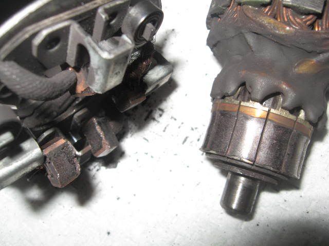
I recently have been having an issue with starting my bike, it was clicking but the starter was cranking intermittently. I took it off for a bench test, it wasn't spinning. I then took it apart and cleaned all the connections at armature commutator, with fine grit sandpaper. Afterward i tested any 2 commutator pads with a voltmeter to find out that they all short together, it's like everything is one block of copper. Note that there was no nominal resistance of the copper windings, which would be normal, it showed 0 ohm. I'm perplexed because the commutator doesn't look excessively worn from brush contact.

Anything i should check more before cashing out on a new starter, or another used starter? Can i just get a new armature anywhere nowadays for this bike?

Thanks
 
The armature is out there, but on which bike's starting motor-I don't know, because I haven't seen many armature failures...
You can likely get brushes somewhere as parts... but I would say the motor won't spin "intermittently" if there was any issue with the windings. I'm not always right and lots of unlikely stuff might be the problem but I have to go with the obvious over and over ... the Brushes and connections as the most likely and I see this a lot, given that the starter button and solenoid are indeed ok and the starter motor fails a free-running bench test ...
You've been "cleaning it up" but you didn't say you bench-tested it again. I would,
re-assemble and test the motor again on a battery...ie:connect a thick wire to Positive Terminal and push hard the motor's case onto the negative.
and you know to Hold on Tight! ... (and no flammable vapours around ok?)

because....I'm not sure a motorcycle has the capacity in its puny battery or stator to hurt these windings...
However,
if the armature has got a ground deep in the windings, you will still get a Fancy Spark at the negative.
Multimeters are not much use beyond continuity here . You might like to try with the ol' fashioned 12volt test lamp and note it's brightness, voltage drops etc but really, they are simple enough to trobleshoot without a meter.
 
Last edited:
I did do a bench test on it, however when i connected the battery positive to the positive of the starter and grounded the housing i got a big loud spark :)) Which made me test the continuity with a voltmeter and sure enough i found that the positive nut of the starter shorted to its body (which explains the spark). I later read up about windings on the armature and found out that in no case they should read 0 ohm, which made me think the armature failed on me because all of the commutator pads were connected to each other.

Do you know what is the nominal resistance at the terminals of a functioning starter motor? so i can compare, it should be pretty small.
 
Just get a used one off ebay or salvage yard. The "E" uses a different starter motor than shafties- rear mount is different (see pic- shafty on left). the 650E should be same as 550's and 750's so should be plenty to choose from.
for cross reference, see this http://www.stockers.com/
 
Your tests are not valid

the armature is most likely fine. Check it for grounds and opens with a 120volt test light, and shorts with a growler.

You can't check continuity with a voltmeter

The starter motor is an "educated ground", a high current device, the + post will always read no resistance to ground when if the starter is assembled. Starter motors have large conductors to carry high current you can't read appreciable resistance with an ohmmeter.

If your starter is shorted, it will burn, black and smoking
 
But don't you think the coil windings have to have some resistance that I can measure with an voltmeter?

Moreover, when i took apart the armature i tested the commutator pads for continuity. The pads are supposed to be connected in pairs as far as i understand how brushed motors work. However what i found out with my voltmeter is that any 2 commutator pads are connected to each other, now that just doesn't make sense to me. Am i missing something really basic maybe? I'd hate to get another starter just to find out that i was testing mine improperly.

thanks for your advice and suggestions!
 
But don't you think the coil windings have to have some resistance that I can measure with an voltmeter?

You can't measure ANY resistance with a voltmeter. Hopefully you're actually using a meter that measures voltage AND resistance, and just calling it a voltmeter, but if you're not using the ohmeter function you'll never measure resistance.

Your test isn't really valid anyway. The coil windings are just exactly that: windings. Of wire. Measure the resistance of a length of wire sometime. You'll read VERY close to zero ohms. Same is true for the armature of the starter: coils of wire.

If you really want to make this motor run, take it to a rebuilder. They can do any and all tests and even rewind it for you if necessary. Otherwise you're probably better off picking one up off e-bay.
 
No buts...

The segments are insulated from each other, but connected through the windings, you will read continuity but you are reading through windings of really low resistance. The windings make several "laps" each around the armature, and there is more than one winding connected to each bar.(segment) which windings are powered up is determined by the brush arrangement (if the bars / pads / segments weren't insulated from each other then the electricity wouldn't flow through the windings, it would flow bar to bar and the starter wouldn't turn)

Yes you are missing something really basic, go on the google and look around

One more time, you can't measure resistance with a voltmeter!

Put it back together and test it on the bench, you are going to see sparks, (high current) the starter will jump, it makes a lot of torque so you may want to hold it with a vice. Booster cables and a good battery,One cable to the vice, or case, the other to the stud, (put a nut on the stud first) + or - doesn't matter for this test
 
Last edited:
...
...............
............... The pads are supposed to be connected in pairs as far as i understand how brushed motors work. However what i found out with my voltmeter is that any 2 commutator pads are connected to each other, now that just doesn't make sense to me. Am i missing something really basic maybe?......

I think simple DC motors, like maybe in a toy, might have two pairs of coils (windings) that each are separate (four sections on the commutator).
And simple descriptions of "How DC motor works" may only show one coil (2 sections on commutator).

But a more detailed, higher power DC motor (like a starter motor) has more complicated windings, such that the windings are interconnected.

.
 
The shortest and "least-resistant" path for the electricity will be brush->brush.

It wouldn't matter if the windings were also connected because their sum of "series resistance" will always be much greater than the one or two windings the brushes will connect at the commutator.

The shop manual I have does not bother to include an ohms test. Only a continuity one. However, the manual does include a test for the solenoid coil at 3 ohms...so it's not that they wouldn't include an ohms test, if it were relevant...

however, if you want to try and test ohms at the armature,cross your leads, note the reading. Subtract this reading from any further test. What you would be looking for is a large difference in values found,commutator->opposite commutator

and sure enough i found that the positive nut of the starter shorted to its body
...so you forgot to put the insulator sleeve back on the positive lead where it comes through the shell...that's pretty important!
 
IMG_1057.jpg


Also, when look at the connection there by the commutator bar, can kinda see how, there on any one particular slot of the commutator, it looks like maybe a wire comes from one coil (winding) and another wire goes back out to another. So that would indicate that each slot on the commutator is connected to more than just one coil.
Would have to chip away that epoxy (or whatever) to prove it, but what I see there pretty much supports what I think anyway (sounds like an O.T. discussion.)


.
 
Last edited:
problem solved

problem solved

Hello everyone,

I did test the continuity with the ohmmeter setting of the voltmeter (i'm using this term in a general way). However, it seems that my voltmeter is indeed just not sensitive enough to tell me mOhm. So i ended up bench testing it and sure enough it did spin and appeared to work fine overall.

Thank you all for the insightful and useful comments! The commutator pads are all connected through the various windings of the coil. What threw me off is that my voltmeter just wasn't sensitive to differentiate series resistance of a couple of windings from the resistance of a single winding.

BTW here's a good image explanation of the windings:
http://www.groschopp.com/how-to-check-a-motor-armature/

the second figure from the top really illustrates it all.

Thanks again everyone!!! problem solved!
 
Back
Top