G
Guest
Guest
I'm finally getting back to my bike build after over 2 years of doing nothing. I'm to the point where I'm wiring the bike up from scratch, eliminating most circuits for now just to get the bike running, and then will add in minor stuff like neutral light, oil temp, etc.
I'm planning on going with some K&S left and right controls which are cheap and cannot handle many amps (according to reviewers). I'm debating what all circuits I should switch with a relay.
1. Main relay. I'm going to be doing an RFID ignition, which will switch on a 60 amp relay to enable power to the fuse box where everything will be run from.
2. Kill switch/ignition relay. Should I utilize a relay for the ignitor / starter solenoid circuit? I'm not sure how many amps run through the ignitor, but even the starter solenoid should pull over 3 amps (4 ohm solenoid). The power for the starter solenoid will run through the kill switch and the starter button, although I could separate those out (allow cranking without spark).
3. Headlight. Now I certainly want a relay for this, but if it's just one relay then the full amperage would be going through the hi/low switch (what's the point then?). So I assume I'll want one relay for hi and one for low, and both of them SPDT normally closed so the headlight can be disabled during cranking?
4. Signals. They will be LED so I'm not concerned about that.
5. Horn, if I add one. I'll want to relay this too.
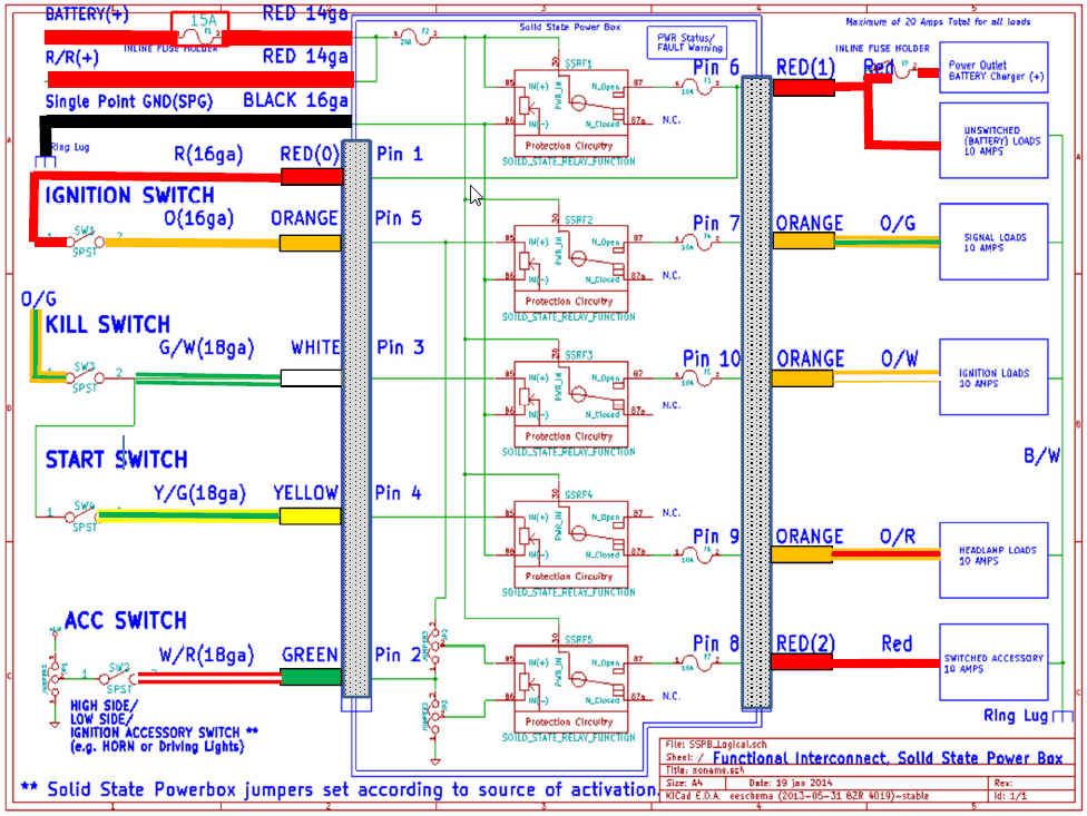
Ugh, this is a lot of relaying going on. Am I way off on this? I've looked at the SSPB (which looks awesome), but honestly I'd want more switched circuits.
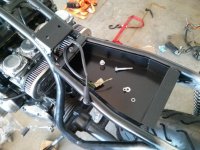
Here's where all of this needs to be crammed in")

I'm planning on going with some K&S left and right controls which are cheap and cannot handle many amps (according to reviewers). I'm debating what all circuits I should switch with a relay.
1. Main relay. I'm going to be doing an RFID ignition, which will switch on a 60 amp relay to enable power to the fuse box where everything will be run from.
2. Kill switch/ignition relay. Should I utilize a relay for the ignitor / starter solenoid circuit? I'm not sure how many amps run through the ignitor, but even the starter solenoid should pull over 3 amps (4 ohm solenoid). The power for the starter solenoid will run through the kill switch and the starter button, although I could separate those out (allow cranking without spark).
3. Headlight. Now I certainly want a relay for this, but if it's just one relay then the full amperage would be going through the hi/low switch (what's the point then?). So I assume I'll want one relay for hi and one for low, and both of them SPDT normally closed so the headlight can be disabled during cranking?
4. Signals. They will be LED so I'm not concerned about that.
5. Horn, if I add one. I'll want to relay this too.
Ugh, this is a lot of relaying going on. Am I way off on this? I've looked at the SSPB (which looks awesome), but honestly I'd want more switched circuits.
Here's where all of this needs to be crammed in
")