

THe stator paper part C, is for doing the R/R checks with a meter. It specifiys using the diode check feature of a meter. (Zuzuki manaul specifys Ohm checks, but that was early 80s, meters now more likley to have diode checks).
The stator paper has me check from r/r output (red) to each of the 3 phases (in both polaritys of the meter), and then has me check from r/r ground (blk/wht) to each 3 of the phases (again in both polarity of the meter).
I can understand that is using the "diode check" feature of the meter to check the diodes.
ANd I understand what the "diode check" function of the meter is. And I understand what the diodes in the R/R are and what they are doing (3 phase, full wave rectification). And I understand that we are checking the diodes (the rectification part of the R/R) and not checking the regulator portion of the R/R. Then the stator papers then say "that is all, if checks out okay, then only thing left is the battery". But...but...but.. have only checked the the rectifier portion of the rectifyer/regulator.
What I am questioning is this:
Why dont we do any checks from the r/r output (red) to the r/r ground in an attempt to check out at least something of the regulator part of the R/R?
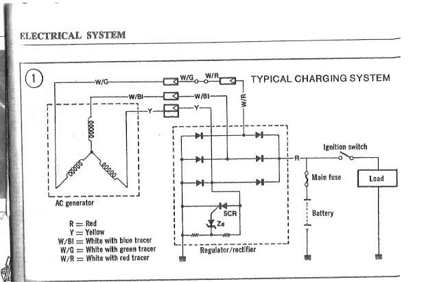
I suspect this schematic of the R/R internals might be somewhat simplified, but using it anyway.....
Looks like if test from output (red) to ground (b/w) that would go thru the one diode and then thru the regulator portion. BUt the regulator portion presents a couple parrallell-series-parrallel branch paths, but still seem to me that a good r/r whould exhibit certain characteristic, and a r/r that had some problem with the regulator portion, like shorted out SCR or blown open ZE or something (dont know what a common problem would be) would exhibit other characteristics.
Oaky, I will admit that I have only a basic understanding of electronics, and little experince or practical knowlodge.
Maybe someone can say, that "NO! there is no way to do any static tests with a meter" on the regulator portion of the R/R.
But the stator papers make it sound like that the test they specify have been a total and complete test of the R/R.
I do see that when checking from ground to yellow that are would be checking that one doide and that the regulator (ZE & SCR) are in parrallell with that doide. SO maybe that is the answer, if regulator part were to be shorted (zero ohms) then would not pass that diode test. BUt if ZE or SCR were blown open the diode test would still pass, ... so again, why dont we test anything from output to ground?
So I am asking, why dont we ... . . . ...... ?
And Then I do it anyway.
My check of my R/R (2 year old Ricks) using the diode check feature of a nice Fluke is:
-Black meter lead to R/R output (red)
and meter red to each r/r phase reads .55, .55, .56 volts
and meter red to r/r ground reads .75 volts
- Then Red meter lead to R/R output (red)
and meter black to each r/r phase reads 2.55 (open) on all
and black red to r/r ground reads 2.55 (open)
And ask if there is any significance there or not?
Maybe someone with a known good R/R can do the checks acraost the red to b/w.
.
The stator paper has me check from r/r output (red) to each of the 3 phases (in both polaritys of the meter), and then has me check from r/r ground (blk/wht) to each 3 of the phases (again in both polarity of the meter).
I can understand that is using the "diode check" feature of the meter to check the diodes.
ANd I understand what the "diode check" function of the meter is. And I understand what the diodes in the R/R are and what they are doing (3 phase, full wave rectification). And I understand that we are checking the diodes (the rectification part of the R/R) and not checking the regulator portion of the R/R. Then the stator papers then say "that is all, if checks out okay, then only thing left is the battery". But...but...but.. have only checked the the rectifier portion of the rectifyer/regulator.
What I am questioning is this:
Why dont we do any checks from the r/r output (red) to the r/r ground in an attempt to check out at least something of the regulator part of the R/R?
I suspect this schematic of the R/R internals might be somewhat simplified, but using it anyway.....
Looks like if test from output (red) to ground (b/w) that would go thru the one diode and then thru the regulator portion. BUt the regulator portion presents a couple parrallell-series-parrallel branch paths, but still seem to me that a good r/r whould exhibit certain characteristic, and a r/r that had some problem with the regulator portion, like shorted out SCR or blown open ZE or something (dont know what a common problem would be) would exhibit other characteristics.
Oaky, I will admit that I have only a basic understanding of electronics, and little experince or practical knowlodge.
Maybe someone can say, that "NO! there is no way to do any static tests with a meter" on the regulator portion of the R/R.
But the stator papers make it sound like that the test they specify have been a total and complete test of the R/R.
I do see that when checking from ground to yellow that are would be checking that one doide and that the regulator (ZE & SCR) are in parrallell with that doide. SO maybe that is the answer, if regulator part were to be shorted (zero ohms) then would not pass that diode test. BUt if ZE or SCR were blown open the diode test would still pass, ... so again, why dont we test anything from output to ground?
So I am asking, why dont we ... . . . ...... ?
And Then I do it anyway.
My check of my R/R (2 year old Ricks) using the diode check feature of a nice Fluke is:
-Black meter lead to R/R output (red)
and meter red to each r/r phase reads .55, .55, .56 volts
and meter red to r/r ground reads .75 volts
- Then Red meter lead to R/R output (red)
and meter black to each r/r phase reads 2.55 (open) on all
and black red to r/r ground reads 2.55 (open)
And ask if there is any significance there or not?
Maybe someone with a known good R/R can do the checks acraost the red to b/w.
.
Last edited:


 /
/