-
Required reading for all forum users!!!
Welcome!
Register to access the full functionality of the GSResources forum. Until you register and activate your account you will not have full forum access, nor will you be able to post or reply to messages.A note to new registrants...
All new forum registrations must be activated via email before you have full access to the forum.A Special Note about Email accounts!
DO NOT SIGN UP USING hotmail, outlook, gmx, sbcglobal, att, bellsouth or email.com. They delete our forum signup emails.A note to old forum members...
I receive numerous requests from people who can no longer log in because their accounts were deleted. As mentioned in the forum FAQ, user accounts are deleted if you haven't logged in for the past 6 months. If you can't log in, then create a new forum account. If you don't get an error message, then check your email account for an activation message. If you get a message stating that the email address is already in use, then your account still exists so follow the instructions in the forum FAQ for resetting your password.Have you forgotten your password or have a new email address? Then read the forum FAQ for details on how to reset it.
Any email requests for "can't log in anymore" problems or "lost my password" problems will be deleted. Read the forum FAQ and follow the instructions there - that's what we have one for...
-
Returning Visitors
If you are a returning visitor who never received your confirmation email, then odds are your email provider is blockinig emails from our server. The only thing that can be done to get around this is you will have to try creating another forum account using an email address from another domain.
If you are a returning visitor to the forum and can't log in using your old forum name and password but used to be able to then chances are your account is deleted. Purges of the databases are done regularly. You will have to create a new forum account and you should be all set.
You should upgrade or use an alternative browser.
BassCliff
Guest
BikeCliff website update
Hi guys,
With the help of Mr. oldryder and Mr. Steve, I've added a page to my little BikeCliff website with some information about the ignition coil upgrade mod.
Direct link here.
Great thread. Thank you all for your input. I think I'm going to try this mod on the next Saturday I have free.
Thank you for your indulgence,
BassCliff
Guest
Guest
that's great info!Hi guys,
With the help of Mr. oldryder and Mr. Steve, I've added a page to my little BikeCliff website with some information about the ignition coil upgrade mod.
Direct link here.
Great thread. Thank you all for your input. I think I'm going to try this mod on the next Saturday I have free.
Thank you for your indulgence,
BassCliff
now, something's telling me you're going to take some pickies of how it's done when you get to trying it out on your bike! :-D
BassCliff
Guest
Have camera, will wrench
that's great info!
now, something's telling me you're going to take some pickies of how it's done when you get to trying it out on your bike! :-D
Sure, why not? I'll keep you informed. Thanks Mr. psyguy.
Thank you for your indulgence,
BassCliff
focus frenzy
Guest
Sure, why not? I'll keep you informed. Thanks Mr. psyguy.
Thank you for your indulgence,
BassCliff
I just did the mod and took some pics!
did it on the project bike that had enough voltage drop it wouldn't start.
(it has new harness and yes I cleaned the switches but still did not like the drop)
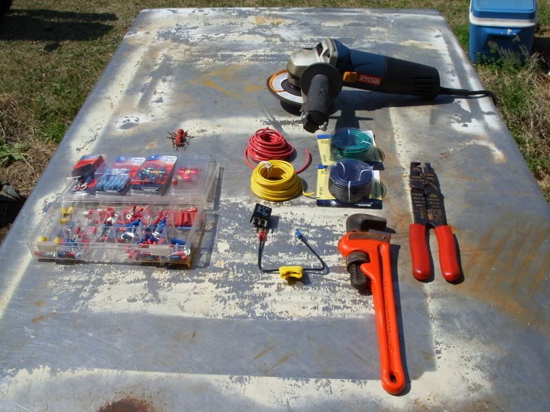
first you need to gather up the needed supplies.
wire, I used 14 gauge and also have a assortment of colors but this can be done with just one color.
connectors. butt, spade and ring are the three type needed I used trick gold plated copper for the connection at the relay as I had it laying around and it looks purdy.
relay. I used a osram mini relay I had salvaged from a bad PDM at work, these are nice and small and rated to 30 amps, more than enough for the job. these also are very reliable, we have some trucks four years old with over 800,000 miles on them and they still have all their original relays.
in-line fuse holder and fuse. i had this cheep one laying around so I used it
I used a capped mini blade fuse holder when I did the mods on my G and prefer to use them.
pic of parts and tools layed out.
picture of relay with wires connected and ready to go.
the power lead (fuse holder) connects to terminal 30 on the relay
the output to the coils connects to terminal 87 on the relay and splits into two female spade connectors on the coil end.
the control wire connects to terminal 85 on the relay
the ground relay connects to terninal 86 on the relay
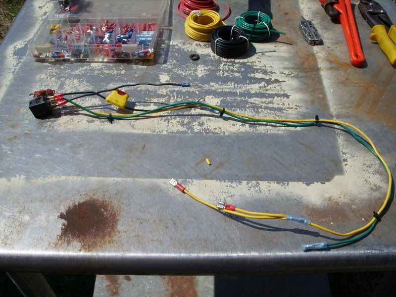
you plug the coil wire (yellow) onto the + terminal on each coil and take the orange with white wires that were connected to the coils and crimp them into the butt connector on the control (green) wire.
early coils had the wire permenantly fixed into the coils so you cut them midway down to the harness plug and use butt connectors instead of the female spade connectors.
you then connect the power feed wire (with fuse holder) to the + battery terminal and the ground to a good ground spot or the ground terminal of the battery.
I tucked the relay up in the protective comer on the harness that goes to the fuse box.

this is a little video clip of the results (this bike has sat for 10 years!)
http://smg.photobucket.com/albums/v495/leonhogan/?action=view¤t=techday3-15005.flv
BassCliff
Guest
You are an encouragement. I'll be ordering parts for my bike soon (front caliper rebuilt kits, shims, etc). I'll be sure to include the parts for this ignition upgrade. Nice work.
I'm glad we don't have ants that big around here. Running over a few of them with your bike would make quite a mess.
Thank you for your indulgence,
BassCliff
catbed
Guest
do i need that green wire if i do this? cant i just relay the power cable and leave the other two wires connected to the coil?
Steve
GS Whisperer
It might help to demystify relays just a little bit. All it is, is a remote-control switch.Where does the green wire go in the relay? and why do the orange and white wires from the coils get connected to it. usually im very electric-savvy but for some reason, i cant get my head around this.
do i need that green wire if i do this? cant i just relay the power cable and leave the other two wires connected to the coil?
The orange/white wire used to provide power to the coils. Now you will use that wire to turn on the relay, so you connect it to the green wire, which is connected to terminal 85 or 86. The other terminal (86 or 85) will need to be connected to ground. What this does for the relay is power the coil that pulls the other contacts together.
Now you take your battery power (through a fuse), connect that to terminal 30. Now run a pair of wires from terminal 87 to where the orange/white wire used to be on the coils. This is your new power source for the coils, but it is controlled by the original wire.
.
saddlewarmer
Guest
catbed
Guest
It might help to demystify relays just a little bit. All it is, is a remote-control switch.
The orange/white wire used to provide power to the coils. Now you will use that wire to turn on the relay, so you connect it to the green wire, which is connected to terminal 85 or 86. The other terminal (86 or 85) will need to be connected to ground. What this does for the relay is power the coil that pulls the other contacts together.
Now you take your battery power (through a fuse), connect that to terminal 30. Now run a pair of wires from terminal 87 to where the orange/white wire used to be on the coils. This is your new power source for the coils, but it is controlled by the original wire.
.
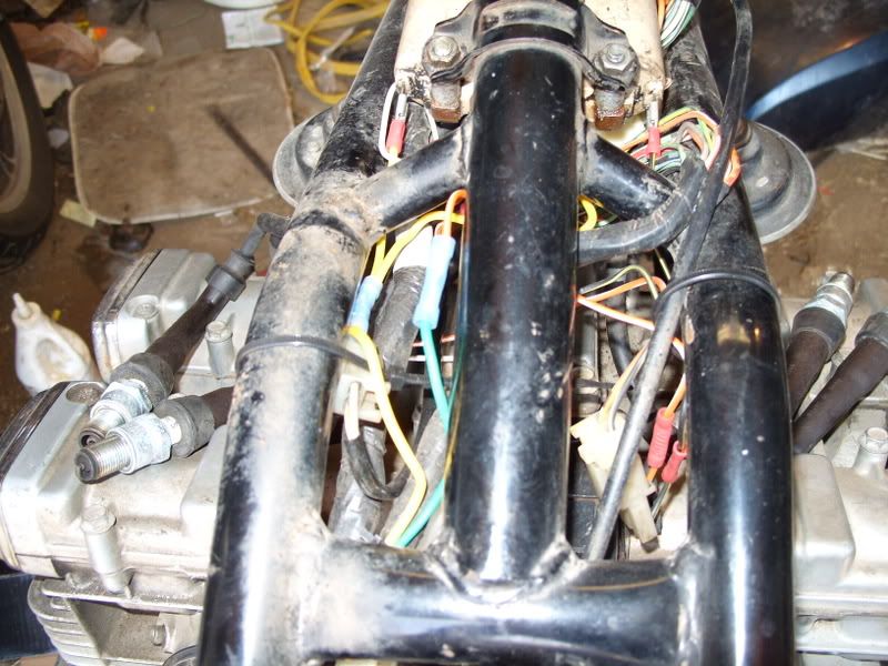
so there are still two stock wires connected to the coils. i was confused because i couldnt see the other connections on the coils in the picture.
Steve
GS Whisperer
The angle grinder cleans gounding points to assure a good connection. :shock:I get the use for all the tools in your picture but the pipe wrench and the angle grinder.
The pipe wrench is to make sure the ground screws are tight. 8-[
.
hp1000s
Guest
...nicely done!The angle grinder cleans gounding points to assure a good connection. :shock:
The pipe wrench is to make sure the ground screws are tight. 8-[
.
focus frenzy
Guest
The angle grinder cleans gounding points to assure a good connection. :shock:
The pipe wrench is to make sure the ground screws are tight. 8-[
.
actualy the grinder was for my toe nails, the next project was trimming my nails.
the pipe wrench was for if the bike failed to start as I could not find where I put my 3lb drillers hammer.
after hooking it up I had checked the spark and it was not a very strong spark, it was a nice shade of blue but was tiny.
both my G with dyna coils and E with accel coils put out fat hot spark.
Kcwiro
Guest
can anyone post the new updated voltage loss data postmod? Certainly interested to know... but as I see it in here the mod basically provides direct junction from the key on position to the coil instead of it looping through everything as before but since we aren't disconnecting anything in that circuit it just has redundency and is also intern more efficient.
Very interesting and cheap.. my buddy and I are going to go for doing this...GOOD READ!
focus frenzy
Guest
can anyone post the new updated voltage loss data postmod? Certainly interested to know... but as I see it in here the mod basically provides direct junction from the key on position to the coil instead of it looping through everything as before but since we aren't disconnecting anything in that circuit it just has redundency and is also intern more efficient.
Very interesting and cheap.. my buddy and I are going to go for doing this...GOOD READ!
DOH!!!! ](*,) I was so happy to hear it run after its long slumber I neglected to take the readings.
I will bring home my good meter from work (the one I took the first readings with) and have the new coil supply volts numbers tomorrow by this time.