That "black/white strip wire" is the ground for the fuse box "mounting plate" (the black panel the fuse box is attached to). as it is only three inches long it shouldn't be hard to find where it attaches.Shoot. There is another black/white strip wire I found. Didn't see it earlier. It is in a bundle that leads to the fuse box. It has an eyelet connector on it, so it that a ground as well? what would that screw to? The wire is only 3in long so it can't reach far.
(referring to the eyelet as seen in this illustration... http://i811.photobucket.com/albums/zz37/teamf4/82 gs1100gk/100_0724.jpg)
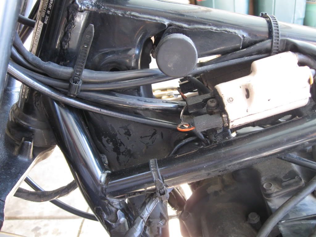
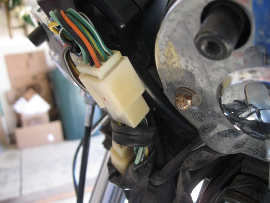
I'm still working on the answer to why the wire was extended. I suspect it was to ground the R/R to the battery. (I haven't got to it as of yet. reason... is my bike is burriedHere is a closer pic of the black wire/white strip. It is coming out of the bottom of the white connector
http://i811.photobucket.com/albums/zz37/teamf4/82 gs1100gk/100_0711.jpg
 )
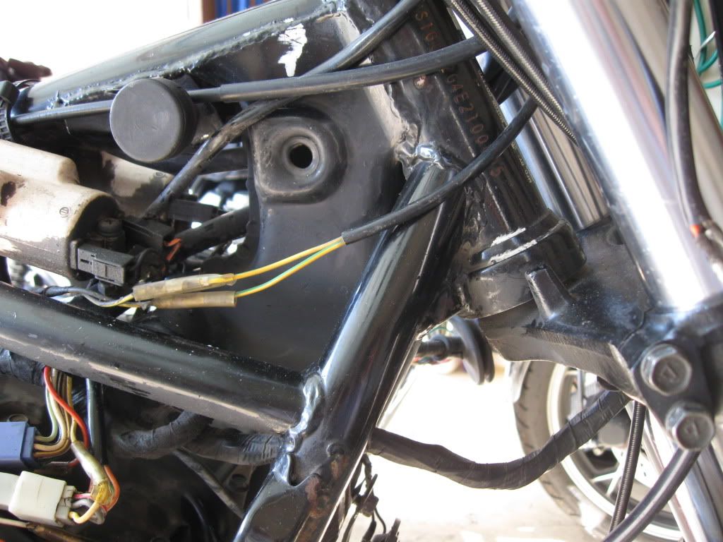
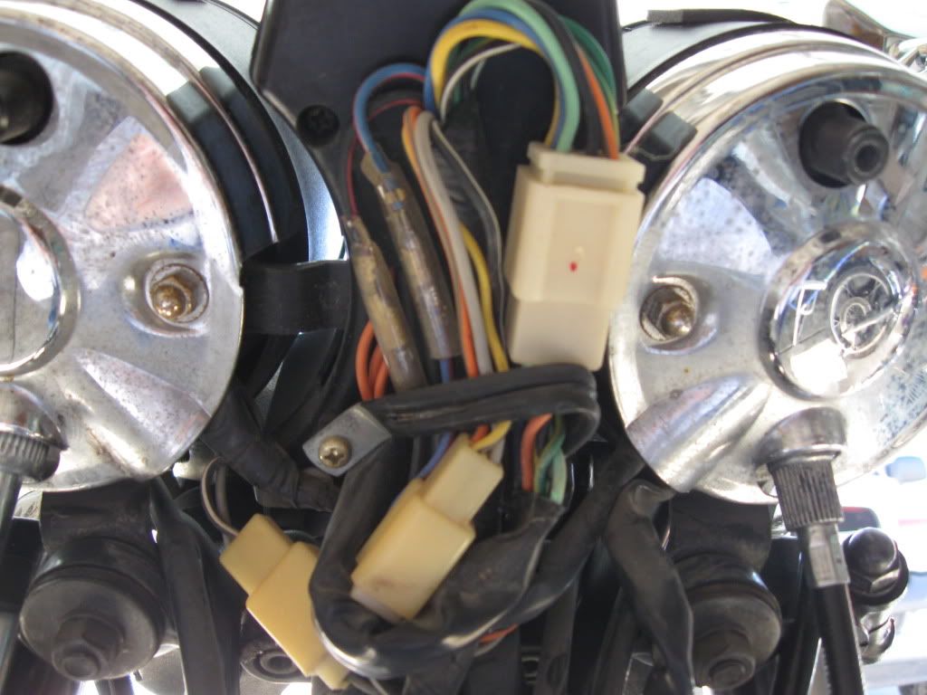
)What color wire(s) is (are) the that blue connected to? <question answered>These 2 pictures show the blue wire coming out with a red wire to a white end connector with a messed up connection for another connector. It's a long line of wire. My finger is pointing to where it comes out of the harness, right before the battery.
http://i811.photobucket.com/albums/zz37/teamf4/82 gs1100gk/100_0719.jpg
More than likely, the reason for the 15 amp fuse blowing, is because of a bad R/R (rectifier/regulator> the aluminum thing with the fins). where is your R/R located? under the battery box, or is it located where Larry is showing His? (Larry's R/R location... http://i345.photobucket.com/albums/p364/Larry_D/motorcycle/IMG_0633.jpg?t=1268825848Here's another close up of the fuse box. It has the amps written above the slot for each one. They go 10, 10, 10, 15, 10.
The second one down keeps popping and then today the 15 is. So both of those keep popping now.
(I will need to know more about your R/R brand/type and possible connector modifications... don't concern yourself with that just yet. )
The orange wire comes from the ignition switch and connects to the top three 10 amp fuses. someone just tapped it to it to run power to some device.I pulled out the connector to get a better picture of the wires. That red one off to the left was just a random one from earlier and looks to be tied into the orange wire.
a clarification if you would please... was that orange/red connection where the "gaggle" of extra red wires are (were) connected?
***done with my post edit. have at it!
Last edited:
 )
)
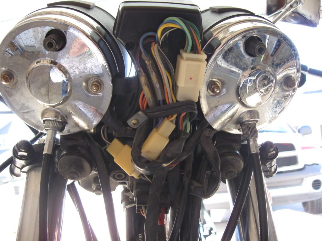

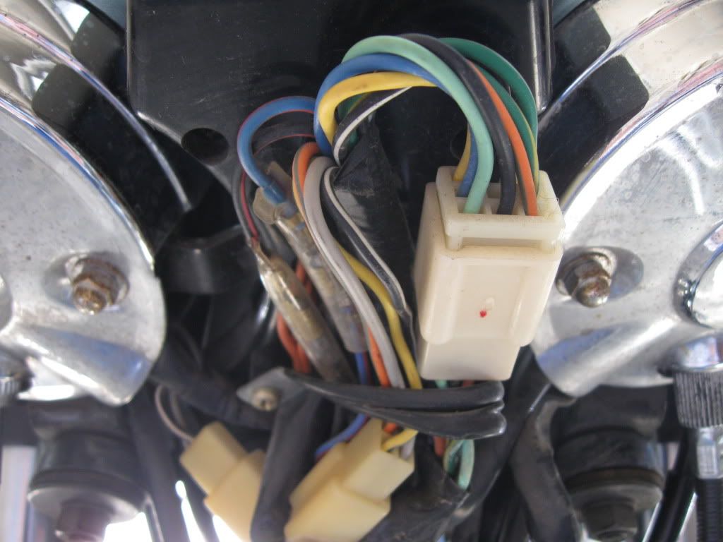


 The blue connector has a light green wire out of it attached to another light green wire. The black wire out of the blue connector is attached to another black wire. There is a grayish wire and an orange/green strip wire.

