Announcement

Collapse
No announcement yet.

Why does Suzuki split R/R + output between ignition and battery?

Collapse
X
 
  • Filter
  • Time
  • Show
Clear All
new posts

    #31
    Originally posted by GSJim View Post
    Interesting. I was just about to order some stuff from Eastern Beaver to install my SH775 regulator. (Why are Furukawa connectors so hard to find and/or out of stock everywhere? Grumble, snarl...). My stator to regulator wiring was cooked, including a melted connector, but the positive wire into the harness looks OK. The regulator on the bike now is an almost new Electrosport which is connected directly to the stator with bullet connectors (shiny new and clean). Because the bike is in pieces for other reasons I bought the SH775 from my local Polaris dealer to upgrade my electrics.

    So your recommendation for installation is to keep the T. Searching shows this this has been debated before.

    Regulator +ive to the harness (solder or shiny new connector).
    Regulator negative to the battery or good frame ground (shiny new ring connector).
    Stator connected directly to the regulator (solder or shiny new connectors). I might use new bullets to match what is already on the stator.

    Thanks.

    Jim
    You missed the Single point grounding posts.

    See GS Charging Health.

    Technical Info posts that are deemed to be important or popular will be placed here for easier access. If you feel a post should be moved from the Technical Info forum to here then PM the Administrator with your request.


    By picking one of the R/R mounting bolts as the single point ground point, the
    R/R(-) wire can be very short, the mounting plate is automatically grounded and
    all of the return current wires can be tied securely together at a single point. Here
    are the connections
    • #1: Ground R/R(-) to case and side plate
    • #2: The shortest wire to a frame bolt
    • #3: The shortest wire to the Battery (-)
    • #4: Connects to the (B/W) harness negative ring lugs (typically the one
    attached at the solenoid mounting bolt). You can leave the other harness
    ground ring lug (B/W) where it normally is picking up the battery box
    ground.
    Last edited by posplayr; 08-14-2013, 12:29 PM.

    Comment


      #32
      Originally posted by Nessism View Post
      Jim,

      Using your updated Stator Paper's guide figured out there was voltage loss between the R/R positive output wire and the battery. Cleaned the brass terminals in the circuit by extracting them from the connector shell and dunking them in acid. Pinched down the female prongs on the terminals and reassembled everything back together. Voltage loss went from more than 1/2 volt down to about 1/8 volt (can't remember exactly). Stupid flashing LED volt meter still doesn't work properly, but the charging system seems to be.
      Ed,
      Most of these connections have very low resistance, but it does not take much to create the voltage drops. It is just not that easy to measure 0.1 ohms resistance but 0.5V is not hard to miss. My thoughts are that with 0.25V there is some definite resistance somewhere due to corrosion and going unchecked it will likely only increase. By driving the voltage drop down to 0,.1V and below then you are giving yourself more time for corrosion to set back in.

      Good job.
      Jim


      P.S.
      Here is a thread where the OP diligently went through chasing down all of the connections and retested as he made progress. You can see how charging voltages and voltages to the coils steadily increased as he drove down the voltages between the R/R and battery. Last he posted he still needed to go after the positive battery connection.

      Last edited by posplayr; 08-14-2013, 12:41 PM.

      Comment


        #33
        Originally posted by posplayr View Post
        You missed the Single point grounding posts.

        See GS Charging Health.

        http://www.thegsresources.com/_forum...+system+health

        Good point. The regulator on the GS650G is bolted to a metal panel that also holds the ignitor. The panel is then bolted to the frame behind the battery box so there is an extra bolt between the regulator and the frame. The regulator sits horizontally and the mounting bolts are vertical and hard to access unless you are lying under the bike looking up.

        I figured the best frame ground was the grounding point under the battery box because it is connected directly to the frame. I could also use the bolt on the other side of the battery box. I will need to figure out which option uses the least wire and is most convenient for inspection and cleaning.

        I have already removed any existing frame grounds and cleaned the terminals and frame with Deoxit and a wire brush.

        Jim
        1981 GS550T (Long gone)
        1983 GS650G (Rolling rebuild is now a full rebuild.)

        Comment


          #34
          Originally posted by GSJim View Post
          Good point. The regulator on the GS650G is bolted to a metal panel that also holds the ignitor. The panel is then bolted to the frame behind the battery box so there is an extra bolt between the regulator and the frame. The regulator sits horizontally and the mounting bolts are vertical and hard to access unless you are lying under the bike looking up.

          Jim
          If you remove battery you'll see the airfilter box is held on to frame by two bolts facing you- the lower one at front is the ideal spot for a common ground point. Run one ground wire up to ignitor and R/r plate, run another direct to battery negative; Depending on your R/R, best to have its ground wire here also. I also add a ground wire from here up to a bolt holding the fuse box to frame to aid headlight power.
          1981 gs650L

          "We are all born ignorant, but you have to work hard to stay stupid" Ben Franklin

          Comment


            #35
            Originally posted by GSJim View Post
            Good point. The regulator on the GS650G is bolted to a metal panel that also holds the ignitor. The panel is then bolted to the frame behind the battery box so there is an extra bolt between the regulator and the frame. The regulator sits horizontally and the mounting bolts are vertical and hard to access unless you are lying under the bike looking up.

            I figured the best frame ground was the grounding point under the battery box because it is connected directly to the frame. I could also use the bolt on the other side of the battery box. I will need to figure out which option uses the least wire and is most convenient for inspection and cleaning.

            I have already removed any existing frame grounds and cleaned the terminals and frame with Deoxit and a wire brush.

            Jim
            The electrical panel and/or battery box on many GS's is rubber mounted, so the ground path goes through the little metal spacers in the center of the grommets. Basically a really bad grounding path. It's much better to run a ground jumper from the R/R to a solid frame point or the battery directly.
            Ed

            To measure is to know.

            Mikuni O-ring Kits For Sale...https://www.thegsresources.com/_foru...ts#post1703182

            Top Newbie Mistakes thread...http://www.thegsresources.com/_forum...d.php?t=171846

            Carb rebuild tutorial...https://gsarchive.bwringer.com/mtsac...d_Tutorial.pdf

            KZ750E Rebuild Thread...http://www.thegsresources.com/_forum...0-Resurrection

            Comment


              #36
              Originally posted by Nessism View Post
              The electrical panel and/or battery box on many GS's is rubber mounted, so the ground path goes through the little metal spacers in the center of the grommets. Basically a really bad grounding path. It's much better to run a ground jumper from the R/R to a solid frame point or the battery directly.
              It's much better to run a ground jumper from the R/R to a solid frame point AND the battery directly.

              tying both as close to the R/R as possible (close means a short R/R(-) wire

              Comment


                #37
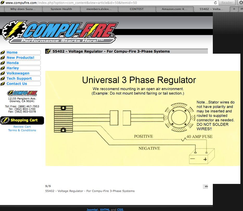
                SO this is news to me. I had my Compufire wired directly to the battery.
                So I should pare back my negative wire on my Compufire as short as possible to the battery negative terminal.
                I should then connect the positive wire on my Compufire to the original red wire that connected the OEM reg\rect?

                Comment


                  #38
                  Jim has been talking about this for some time. He convinced me so I changed back from direct battery feed to the stock Suzuki feed for the Compu-Fire. To tell the truth I did not notice any difference so I'm wondering why I went directly to the battery in the first place. It must have been the nice inline fuse holder that confused the issue.
                  '78 GS1000E, Dyna-S ignition, Dyna Green Coils, K&N pods, Delkevic SS 4-1 exhaust, Dynojet Stage 3 jet kit, Russell SS Brake Lines, Progressive suspension, Compu-Fire series Regulator 55402 and Advmonster cree LED headlight conversion.

                  Comment


                    #39
                    What about the fuse?

                    Originally posted by JEEPRUSTY View Post
                    SO this is news to me. I had my Compufire wired directly to the battery....I should then connect the positive wire on my Compufire to the original red wire that connected the OEM reg\rect?
                    Me too. That's what I am going to do, I have been reading various PosPlayr posts and I noticed you hadn't heard back yet here either. I'd also like to know if it is recommended to fuse it, or keep it like the original R&R was, which wasn't fused. Either way, I will wire it as close to the harness "T" as possible, not down by the connector to the OEM R&R.

                    Originally posted by OldVet66 View Post
                    ...I'm wondering why I went directly to the battery in the first place. It must have been the nice inline fuse holder that confused the issue.
                    For me it was the nice inline fuse holder (albeit with no lid or cap!) and this:


                    And I went to the battery directly since the R&R charges the battery, well that and runs the rest of the electrical system. I assumed that a better charged battery that also acts as a buffer/sort of capacitor to smooth the spiky voltage from the R&R was the place from which the electrical system draws its power, and less voltage drop/current loss from the R&R to the battery would provide the best case scenario...Stator>R&R>battery>fuse box>electrical loads, but I failed to consider that the R&R also provides power directly to the bike while running via the "T" and if we go to the battery directly then it all has to go through the main fuse then to the loads, stressing the fuse box and possibly leaving us stranded.

                    Best if the R&R connects back into the main harness to provide the power to the bike and charge the battery with what's left, and as long as the connections are all clean and the SPG method is used, there should be ample power left to charge, right?

                    My concern is what buffers/smooths the voltage from the R&R in this scenario and what about protection from a short to ground? I blew a whole bunch of LED's when my original R&R kicked the proverbial bucket...Does the battery somehow buffer it as well since it's connected through the T? I don't understand how. Perhaps the FET based power from the Compufire is clean/smooth enough that we don't worry about spikes, but what if it shorts to ground? What will protect the rest of the system, or keep the smoke from exiting the wires?

                    Should we be using that fancy fuse that came with the R&R in-line to the red wire harness or just wire it direct? It was a 40Amp fuse, I changed it out to a 20Amp, as 40 I'm told is way too much.
                    Attached Files
                    ----------------------------------------------------------------
                    2014 BMW F800GSA | 1981 GS850GX | 1982 GS750T (now the son-in-laws) | 1983 GS750ES | 1983 Honda V45 Magna (needs some love) | 1980 Yamaha GT80 and LB80 "Chappy" | 1973 and 1975 Honda XL250 projects

                    Comment


                      #40
                      Originally posted by mikerophone View Post
                      Me too. That's what I am going to do, I have been reading various PosPlayr posts and I noticed you hadn't heard back yet here either. I'd also like to know if it is recommended to fuse it, or keep it like the original R&R was, which wasn't fused. Either way, I will wire it as close to the harness "T" as possible, not down by the connector to the OEM R&R.


                      For me it was the nice inline fuse holder (albeit with no lid or cap!) and this:


                      And I went to the battery directly since the R&R charges the battery, well that and runs the rest of the electrical system. I assumed that a better charged battery that also acts as a buffer/sort of capacitor to smooth the spiky voltage from the R&R was the place from which the electrical system draws its power, and less voltage drop/current loss from the R&R to the battery would provide the best case scenario...Stator>R&R>battery>fuse box>electrical loads, but I failed to consider that the R&R also provides power directly to the bike while running via the "T" and if we go to the battery directly then it all has to go through the main fuse then to the loads, stressing the fuse box and possibly leaving us stranded.

                      Best if the R&R connects back into the main harness to provide the power to the bike and charge the battery with what's left, and as long as the connections are all clean and the SPG method is used, there should be ample power left to charge, right?

                      My concern is what buffers/smooths the voltage from the R&R in this scenario and what about protection from a short to ground? I blew a whole bunch of LED's when my original R&R kicked the proverbial bucket...Does the battery somehow buffer it as well since it's connected through the T? I don't understand how. Perhaps the FET based power from the Compufire is clean/smooth enough that we don't worry about spikes, but what if it shorts to ground? What will protect the rest of the system, or keep the smoke from exiting the wires?

                      Should we be using that fancy fuse that came with the R&R in-line to the red wire harness or just wire it direct? It was a 40Amp fuse, I changed it out to a 20Amp, as 40 I'm told is way too much.
                      I think you have your self a little confused. The R/R is always in parallel to the Battery in either case. It it is not then you will never charge the battery. The question is
                      A.) where do you put the fuse to protect the bike from the battery shorts and
                      B.) where do you tap off from the battery R/R to power the rest of the bike.

                      The OEM way and the one I recommend is the only one where the current flowing between the battery and R/R is only charging current. That minimizes voltage drops keeping your battery charging at the highest voltage possible.

                      The compufire drawing ignores how you power the bike. It looks good on the surface but it is "too simple"

                      Comment


                        #41
                        Originally posted by posplayr View Post
                        I think you have your self a little confused.
                        Easily done this time of night for me.

                        Originally posted by posplayr View Post
                        ...where the current flowing between the battery and R/R is only charging current.
                        So that is at the factory "T" point? Add the in-line fuse there?

                        Thanks for your (continued) help and support to the mere mortals of electrical/technical knowledge here like myself!
                        ----------------------------------------------------------------
                        2014 BMW F800GSA | 1981 GS850GX | 1982 GS750T (now the son-in-laws) | 1983 GS750ES | 1983 Honda V45 Magna (needs some love) | 1980 Yamaha GT80 and LB80 "Chappy" | 1973 and 1975 Honda XL250 projects

                        Comment


                          #42
                          Wait - I want another stab at it.


                          Originally posted by posplayr View Post
                          The question is
                          A.) where do you put the fuse to protect the bike from the battery shorts and
                          B.) where do you tap off from the battery R/R to power the rest of the bike.
                          I love it, you're like the Zen Master at the top of a mountain where a mortal, non-technical noob like me scales the top to ask a question that to them is difficult and when posed to the Master, he returns with deeper, even more technical questions as his answers! Helping us understand the deeper meaning behind all of this!

                          So I'll take a stab at it;

                          A.) where do you put the fuse to protect the bike from the battery shorts? At the battery?
                          B.) where do you tap off from the battery R/R to power the rest of the bike. At the "T"? The part "battery R/R" has me confused...

                          Help men Zen Master Pos, enlighten me or kick me off the mountain?
                          ----------------------------------------------------------------
                          2014 BMW F800GSA | 1981 GS850GX | 1982 GS750T (now the son-in-laws) | 1983 GS750ES | 1983 Honda V45 Magna (needs some love) | 1980 Yamaha GT80 and LB80 "Chappy" | 1973 and 1975 Honda XL250 projects

                          Comment


                            #43
                            Originally posted by mikerophone View Post
                            Wait - I want another stab at it.


                            I love it, you're like the Zen Master at the top of a mountain where a mortal, non-technical noob like me scales the top to ask a question that to them is difficult and when posed to the Master, he returns with deeper, even more technical questions as his answers! Helping us understand the deeper meaning behind all of this!

                            So I'll take a stab at it;

                            A.) where do you put the fuse to protect the bike from the battery shorts? At the battery?
                            B.) where do you tap off from the battery R/R to power the rest of the bike. At the "T"? The part "battery R/R" has me confused...

                            Help men Zen Master Pos, enlighten me or kick me off the mountain?

                            The answer to the Questions:
                            A.) At the battery yes, but more specifically between the battery and the "T" , because the "T" is really the point that brings the two sources together ( battery and R/R output). If you short anything connected to the "T" a lot of current will try and flow from the battery, through the "T" to wherever the short is. That fuse limits that current to a safe level so the the wiring in the harness will not melt.

                            The R/R output doesn't need to be fused here as it is fused down stream in each of IGNITION, HEADLAMP,SIGNAL. The real reason for the main battery fuse is in case the R/R shorts, it is directly across the battery and you will have a fire.

                            B.) Yes you Tap off of the "T" for all currents. In contrast If you tap off of the battery +, then all of the R/R current has to run from the R/R(+) to the battery (+) and then go on to it's final load. That means the full R/R current (15 amps) has to all run between the R/R(+) and the Battery(+) to get to the load. That creates the biggest voltage drop possible for a given about of connector resistance.

                            If you pull current from the "T", then the current from "T" to battery (which includes fuse box and big bullet connector) only carries 3-4 amps maximum with a corresponding drop in the voltage drops meaning the battery voltage will be closer to the R/R output voltage.

                            The construction of the "T" on the positive side, is basically the same as a Single Point Ground on the ground side. It minimizes the sharing of currents, by splitting the currents as close to the source or return as possible. This avoids sharing of currents.

                            In the case of the "T" it is no sharing of load current with charging current between battery and R/R. You will have to study the examples and ask specific questions about them, because my answers are going to get more theoretical which probably doesnt help.

                            There is nothing really mysterious, you just have to understand the splitting of currents and the desire to reduce the current between battery and R/R so that the voltage drops are less.

                            This is what the revised Phase A is trying to minimize.

                            enst
                            Last edited by posplayr; 08-05-2014, 01:26 AM.

                            Comment


                              #44
                              Thank you Posplayr - I do appreciate your thorough, concise response and direction. Thanks for not getting too theoretical on me - it took a few times reading this as it was... Makes sense to me now, especially when compared to the SPG on the ground side. I can wrap my head around that.

                              I'll tap the bit from the R/R into the harness at the "T" and add that fuse between there and the battery, checking/cleaning connections and will solder/wrap any new connections and check voltage drop before and after as well as resistance and call it good for now!
                              ----------------------------------------------------------------
                              2014 BMW F800GSA | 1981 GS850GX | 1982 GS750T (now the son-in-laws) | 1983 GS750ES | 1983 Honda V45 Magna (needs some love) | 1980 Yamaha GT80 and LB80 "Chappy" | 1973 and 1975 Honda XL250 projects

                              Comment


                                #45
                                I have a question on all this, I've read through everything and I think I have a good grasp and understand why things are they way they are. But when I checked voltage drop with a multimeter I had .5v from the bullet connector coming out of the harness into the ignition key switch. As far as I know there is no other contacts so that says the wiring has the resistance built in. Now will this show up in case of bad grounds or is this wire just degraded?

                                Comment

                                Working...
                                X