You could also simply delete the airbox cover if you need more air...
Announcement
Collapse
No announcement yet.
1981 gs750 (gs750e) Retro Racer project
Collapse
X
-
The 1100 Katana moved from the two holes you have to one larger hole between the 1982 and 1983 model years.Originally posted by LarsKroghStea View Post
You could also simply delete the airbox cover if you need more air...
-
Originally posted by LightsOut View PostSome impressive fabrication going into this bike. It's going to be really cool by the looks of it.
Is that the standard airbox/filter for the 750? Curious since my '82 550 has a completely different design. I've been toying with the idea of having one big automotive style cone filter like that attached to the "front" airbox as something in-between proper airbox setup and pods. (Ditching the rear part of the airbox, just the filter)
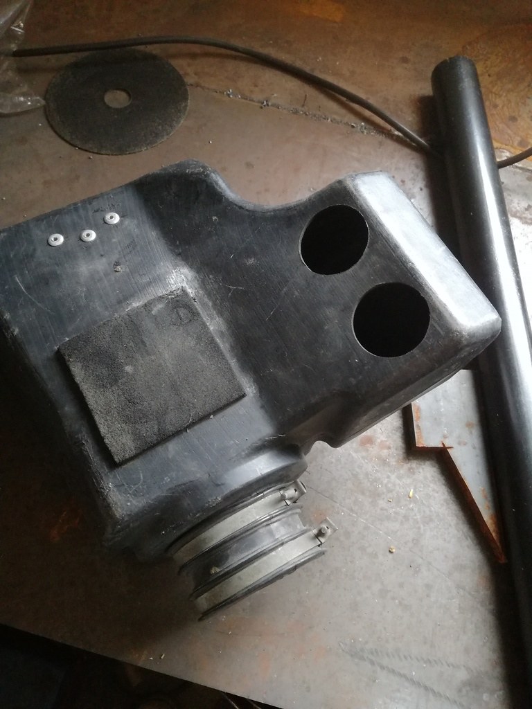 luftfilter by Lars Krogh-Stea, on Flickr
It's the original filter/airbox/plenum arrangement. I knew I didn't want pods, as I wantet to keep the plenum (the box between this one and the carburettors). Then I thought of getting rid of the airbox, but it made it harder to attach the K&N filter. This could be done with a short connecting tube I think, but I optet to keep the airbox as I changed my design plans and went for side covers. I then did some research to descide wther or not to make the holes underneath larger. No definitive answer. I have larger carburettors and a freer flowing exhaust, so I might end up needing more air, but I wont make the holes larger until I know for sure. The bike ran pretty well with this setup, so I'll probably keep it like it is.
Leave a comment:
-
You might try but beware that this will probably disturb your AFR ratio and you could be spending a lot of time getting it right...Originally posted by LightsOut View PostSome impressive fabrication going into this bike. It's going to be really cool by the looks of it.
Is that the standard airbox/filter for the 750? Curious since my '82 550 has a completely different design. I've been toying with the idea of having one big automotive style cone filter like that attached to the "front" airbox as something in-between proper airbox setup and pods. (Ditching the rear part of the airbox, just the filter)
Leave a comment:
-
 Guest repliedSome impressive fabrication going into this bike. It's going to be really cool by the looks of it.
Is that the standard airbox/filter for the 750? Curious since my '82 550 has a completely different design. I've been toying with the idea of having one big automotive style cone filter like that attached to the "front" airbox as something in-between proper airbox setup and pods. (Ditching the rear part of the airbox, just the filter)
Leave a comment:
-
I read through your thread on the GS and got the pictureOriginally posted by John Kat View PostOn my GS 1000 with the GSXR engine, I turned the battery around and fitted the fuse box and the ECU in front of the battery.
I'll try to get a picture for you. Thanks for the input
Leave a comment:
-
On my GS 1000 with the GSXR engine, I turned the battery around and fitted the fuse box and the ECU in front of the battery.
I'll try to get a picture for you.
Leave a comment:
-
I'll also throw in a cuple of picture of how the bike looks now. Putting the headlight, carburettors and airbox on really made it look a lot closer to beeing a rideable bike I've decided to powdercoat the rearsets black as I think they stand out too much from the rest of the bike.
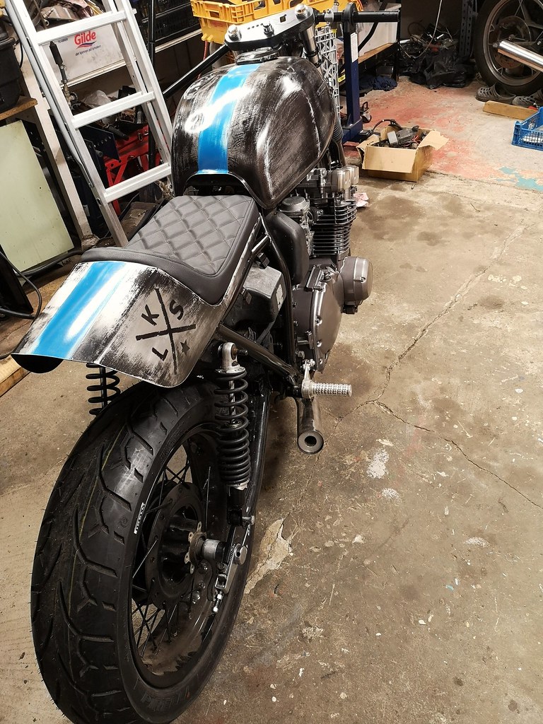 Bike by Lars Krogh-Stea, on Flickr
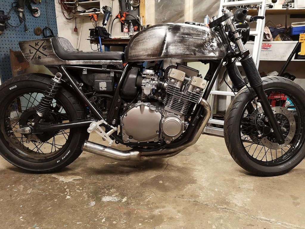 Bike by Lars Krogh-Stea, on Flickr
Leave a comment:
-
In my mind there would be room for electronics under the seat, but when the airbox was in place, there wasn't even room for the seat :P
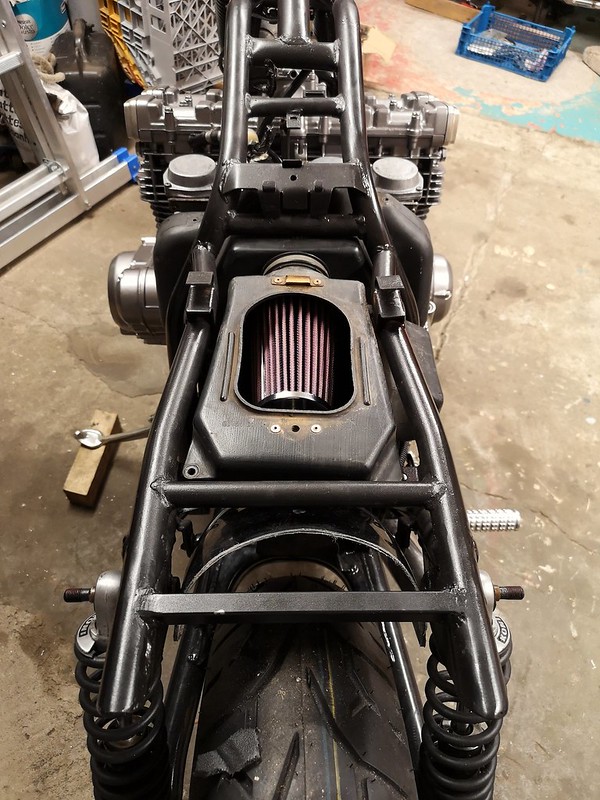 Filter by Lars Krogh-Stea, on Flickr
I've used the original seat "hinge" and turned it upside down like this
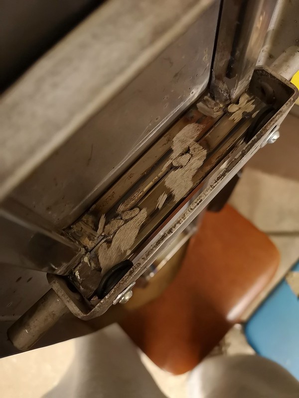 Seat by Lars Krogh-Stea, on Flickr
I'll have to modify it by grinding off the square bar and weld a new round bar directly on the seat frame to get the seat at the right hight.
Any way, that opens up a new problem; where to put the m-unit and the other electronics. I see there's plenty of room on both sides of the batterytray. I'm thinking of making a new tray with a deviding section in the middle. Then the battery will go to the right and the rest of the elctronics will go on the left side. Has anyone done this before? Please post a link to your build thread, and maybe I'll save som time doing trial and error work
This is how it looks now:
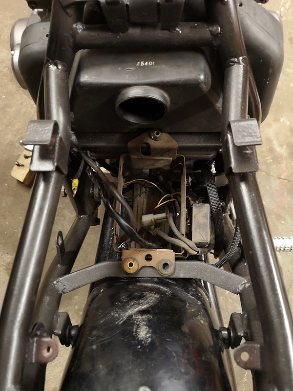 Batterycase by Lars Krogh-Stea, on Flickr
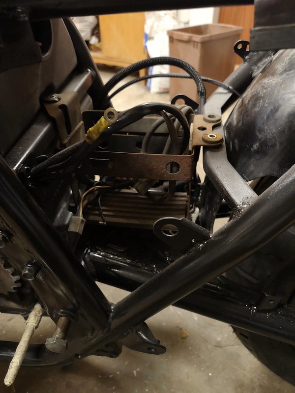 Battery case by Lars Krogh-Stea, on Flickr
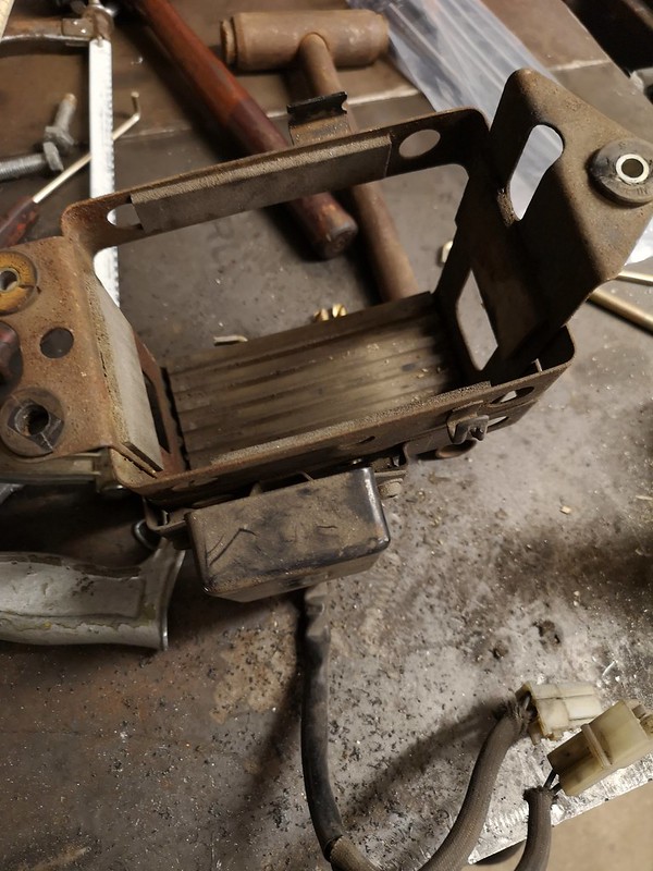 Battery case by Lars Krogh-Stea, on Flickr
Leave a comment:
-
There is a downside to having the bike 1,5 hours drive away. Sometimes I plan something and impatiently order the parts, and when they arrive it doesn't quite turn out as I wanted.
I was planning to use mini switches like on the image below on both sides so I ordered a set of these:

But with the new Domino throttlecontrol there was very little room left on the clipon:
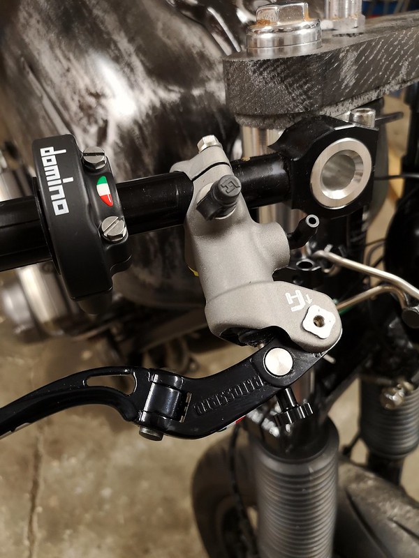 Bike by Lars Krogh-Stea, on Flickr
I have some of these switches laying around, so I'll take som if the plastic I used to prototype the fork triple to make someting similar to the Motogadget switch cluster. Ideally there will be three pushbuttons som I can control the Motoscope mini from the handlebar as well.

Leave a comment:
-
Made a small "bending jig" as I wanted to try out some different ideas for the headlight mount. The first version had an extra loop for mounting the mini blinkers. I thought it looked too cluttered so I removed it.
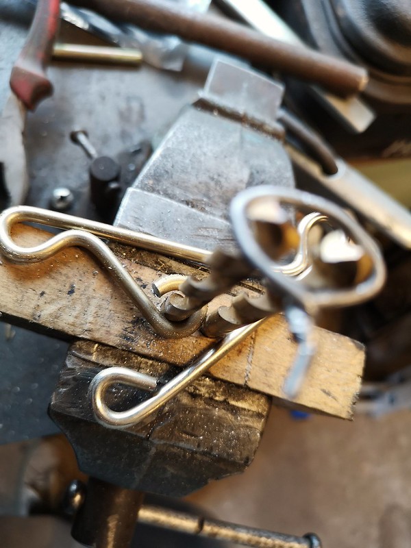 Mount by Lars Krogh-Stea, on Flickr
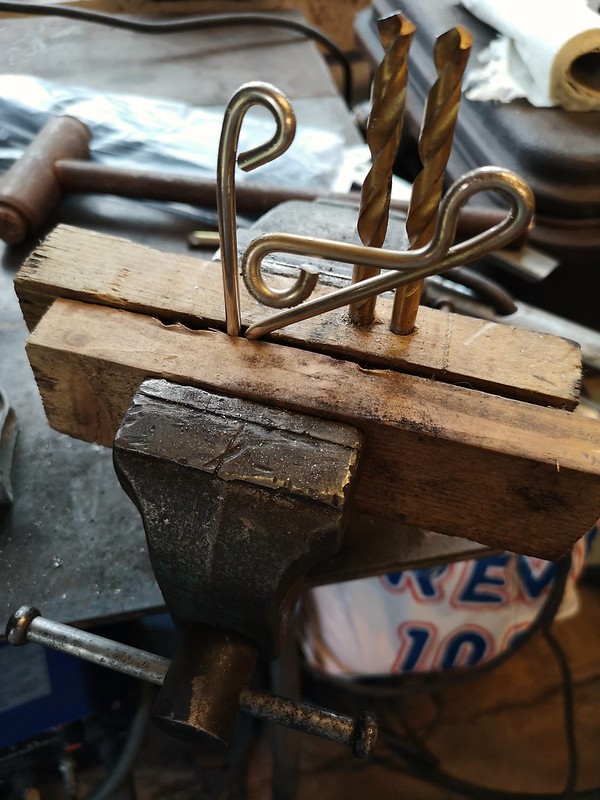 Mount by Lars Krogh-Stea, on Flickr
This is how it turned out with just the loop for the headlight. Not sure if I should powdercoat the clear or black..
 Mount by Lars Krogh-Stea, on Flickr
 Mount by Lars Krogh-Stea, on Flickr
Leave a comment:
-
I posted the wiring diagram in the electrical section and got some pointers and ideas. This is the final rendition of the diagram. The wires are not to scale, either by length or thickness, but the diagram shows how things will be connected to eachother. The turn light switch is a returning two way switch, the others are push buttons.
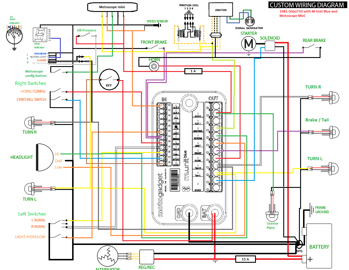 Noisemaker_koblingsskjema by Lars Krogh-Stea, on Flickr
Leave a comment:
-
Originally posted by T8erbug View PostI like it so far! I think it's cool you're using your router table to prototype some of the parts. I have a Shapeoko 3 and use it from time to time on stuff like this. Let me know how that aluminum piece looks after some time in the exhaust. I've been told not to mix stainless parts with aluminum parts unless one or the other has been coated (paint or some other insulator). Galvanic corrosion occurs when the two are in direct contact. I've never seen the affect of it personally but I'm curious to see what happens after a while. Let us know if there are any signs of corrosion or if it's not a big deal!
Thanks I didn't think about the reactivity between metals, but it makes sense. There's not much left of the driving season here, som I'm lucky if I get to test it this year.. But I will keep an eye on it and post pictures if anything interesting happens.
Leave a comment:
-
 Guest repliedI like it so far! I think it's cool you're using your router table to prototype some of the parts. I have a Shapeoko 3 and use it from time to time on stuff like this. Let me know how that aluminum piece looks after some time in the exhaust. I've been told not to mix stainless parts with aluminum parts unless one or the other has been coated (paint or some other insulator). Galvanic corrosion occurs when the two are in direct contact. I've never seen the affect of it personally but I'm curious to see what happens after a while. Let us know if there are any signs of corrosion or if it's not a big deal!
Leave a comment:
-
Hi John
I've made a new diagram with the 15 amp fuse for the charging circuit and some other modifications. All ground is now leading back to the battery via wires, the oil pressure wiring is corrected and the alternator has three wires. The m-lock is really cool and i have an rfid-circuit laying that a was planning to use. Since I have the M-unit blue I'll use the bluetooth for keyless. I'll check out your builds later
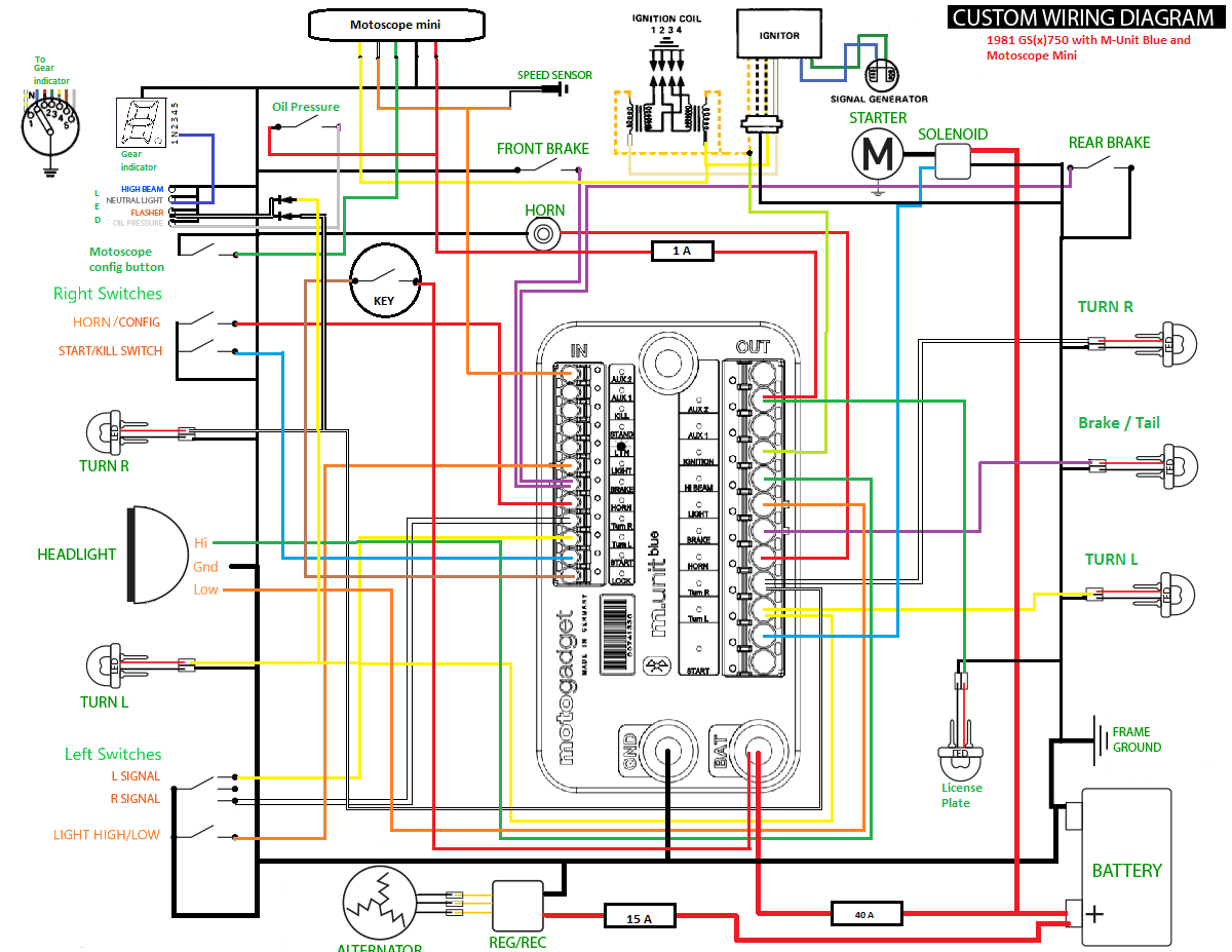 Noisemaker_koblingsskjema by Lars Krogh-Stea, on Flickr
Leave a comment:
-
Hi Lars,
The original wiring has a 15 amp fuse between the regulator and the battery.
It's a separate fuse as the other circuits have their own fuse.
It's mandatory as you could have a short say from a headlamp that would kill you regulator immediately.
Have you considered using the M-Lock from Motogadget?
I installed one yesterday and it works great.
BTW I believe you should also consider the diagram from a wiring harness perspective.
One for the rear of the bike, one for the front , one for the dashboard etc...
Great job!
Leave a comment:
.png)
Leave a comment: