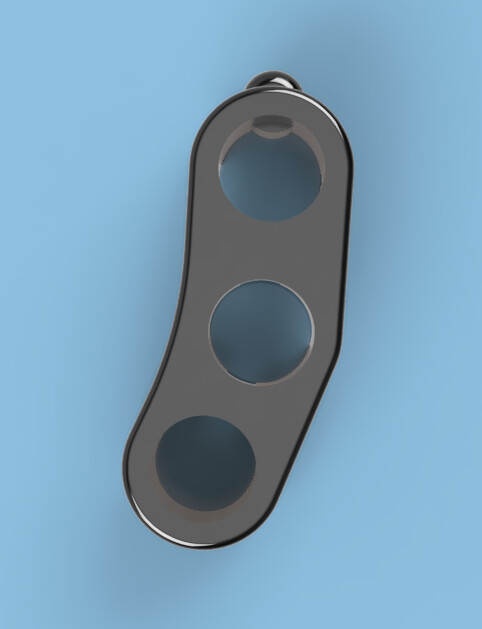
I don't know if this makes sense to you, but I wanted to see if I could fit the Motoscope mini into the GSXR-triple. When I bought the Mini, the plan was to use the original front. Then the new triple would have looked like this:
 1ce10b547c10b4652240c67235888d93 by Lars Krogh-Stea, on Flickr
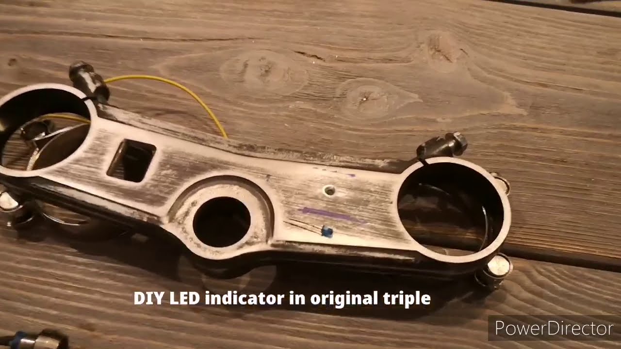
There isn't room to place the Mini in the center of the Gixxer triple, but there is room for it on the opposite side from the gear indicator. I've cut a piece of paper the same size as the Mini, put it on the backside of the triple to position it between the support ridges. Then I've flipped the picture and layered it with opacity on top of the other picture.. Like this:
Backside:
 Triple by Lars Krogh-Stea, on Flickr
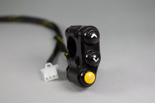
Frontside:
 mini by Lars Krogh-Stea, on Flickr
It doesn't look as cool as when it's mounted in the center, but until I have access to a cnc router again it must be good enough..
I think it would look better with the instrument lights under the Mini.
Not sure of how I want to do this, so I'm open for suggestions
1ce10b547c10b4652240c67235888d93 by Lars Krogh-Stea, on FlickrThere isn't room to place the Mini in the center of the Gixxer triple, but there is room for it on the opposite side from the gear indicator. I've cut a piece of paper the same size as the Mini, put it on the backside of the triple to position it between the support ridges. Then I've flipped the picture and layered it with opacity on top of the other picture.. Like this:
Backside:
Triple by Lars Krogh-Stea, on FlickrFrontside:
mini by Lars Krogh-Stea, on FlickrIt doesn't look as cool as when it's mounted in the center, but until I have access to a cnc router again it must be good enough..
I think it would look better with the instrument lights under the Mini.
Not sure of how I want to do this, so I'm open for suggestions

 )
)


Comment