• Required reading for all forum users!!!

    Welcome!
    Register to access the full functionality of the GSResources forum. Until you register and activate your account you will not have full forum access, nor will you be able to post or reply to messages.

    A note to new registrants...
    All new forum registrations must be activated via email before you have full access to the forum.

    A Special Note about Email accounts!
    DO NOT SIGN UP USING hotmail, outlook, gmx, sbcglobal, att, bellsouth or email.com. They delete our forum signup emails.

    A note to old forum members...
    I receive numerous requests from people who can no longer log in because their accounts were deleted. As mentioned in the forum FAQ, user accounts are deleted if you haven't logged in for the past 6 months. If you can't log in, then create a new forum account. If you don't get an error message, then check your email account for an activation message. If you get a message stating that the email address is already in use, then your account still exists so follow the instructions in the forum FAQ for resetting your password.

    Have you forgotten your password or have a new email address? Then read the forum FAQ for details on how to reset it.

    Any email requests for "can't log in anymore" problems or "lost my password" problems will be deleted. Read the forum FAQ and follow the instructions there - that's what we have one for...

  • Returning Visitors

    If you are a returning visitor who never received your confirmation email, then odds are your email provider is blockinig emails from our server. The only thing that can be done to get around this is you will have to try creating another forum account using an email address from another domain.

    If you are a returning visitor to the forum and can't log in using your old forum name and password but used to be able to then chances are your account is deleted. Purges of the databases are done regularly. You will have to create a new forum account and you should be all set.

1150 3.5" wheel in an 1100 swingarm

  • Thread starter Thread starter jwhelan65
  • Start date Start date
Not sure how you get the same offset with a different sized wheel unless it is not on center. :confused:

The formula is based on the fact that the rear wheel is centered no matter how you get there and it matches the data from "known" good setups :rolleyes:. At least it matches the 4 references I listed.

I'm not saying your wheel is not centered, but how would you explain needing the same offset for 4.0" and 4.5" and the counter sprocket offset being about 1/2 way between 5.5" and 4.5" wheels? The only exceptions to this formula are variations in rear sprocket offsets or sprocket carrier milling.
This is getting fun:cool:
Joke aside, I believe the great Suzuki engineers had only one god : cost reduction!
The secret to that is to reuse the same parts over and over again despite the model changes.
In order to do so they design not only the current model but as much as possible the next generation model.
The chain offset was thus probably decided to be larger than needed for the 3.5" wheel on the GSXR 750 G but also larger than needed to accomodate the 4" wheel of the GSXR 1100 G/H to ultimately take the 4.5" wheels of the GSXR 1100 J and then K.
That's why the rear wheel sprocket carriers are different for some of these models as far as I know.
In the end I suppose it was less costly than re-designing the engine cases?
The centering of the chain in the available space between the frame and the tire was thus not one of their objectives.
That's my .02 $ opinion.
 
I'm not saying your wheel is not centered, but how would you explain needing the same offset for 4.0" and 4.5" and the counter sprocket offset being about 1/2 way between 5.5" and 4.5" wheels? The only exceptions to this formula are variations in rear sprocket offsets or sprocket carrier milling.

I believe the answer is that the offset is not determined by wheel width. The offset difference is determined by the position of the outer bearing face on the drive side and the width of the sprocket carrier, which may or may not be directly related to the rim width. On the 1150 wheel I have, the outer bearing face is 4mm outboard of the 1100 wheel measured to wheel center. Since I am using the same sprocket carrier, the sprocket is also 4mm outboard of the 1100 wheel. Likewise, the rotor is 9mm inboard of the 1100 wheel measured to center of wheel.

Thanks,
Joe
 
This is getting fun:cool:
Joke aside, I believe the great Suzuki engineers had only one god : cost reduction!
The secret to that is to reuse the same parts over and over again despite the model changes.
In order to do so they design not only the current model but as much as possible the next generation model.
The chain offset was thus probably decided to be larger than needed for the 3.5" wheel on the GSXR 750 G but also larger than needed to accomodate the 4" wheel of the GSXR 1100 G/H to ultimately take the 4.5" wheels of the GSXR 1100 J and then K.
That's why the rear wheel sprocket carriers are different for some of these models as far as I know.
In the end I suppose it was less costly than re-designing the engine cases?
The centering of the chain in the available space between the frame and the tire was thus not one of their objectives.
That's my .02 $ opinion.

John,
There would have to be an explanation that was unique to your setup as all the other data supports the simple formula applying to for 5.5", 4.5",4", and 3.5": wheels.
I know mine ended up within about 0.040", Ray's 6mm is within 0.014", and Joe Nardy's 4mm is within 0.032". Those are all too close to coincidently just happen to match this simple formula.

I'm sure that Katman's setups are just centering the chain as he has so little room and pays so much attention to it.
For mine I believe I have 4.5 and 4 mm side to side (frame to chain and chain to tire). Granted side wall width does not go down exactly in proportion to rim width and so variation in the size of the tire on the rim will can change the amount of space the chain has for clearance.
Jim
 
Last edited:
I believe the answer is that the offset is not determined by wheel width. The offset difference is determined by the position of the outer bearing face on the drive side and the width of the sprocket carrier, which may or may not be directly related to the rim width. On the 1150 wheel I have, the outer bearing face is 4mm outboard of the 1100 wheel measured to wheel center. Since I am using the same sprocket carrier, the sprocket is also 4mm outboard of the 1100 wheel. Likewise, the rotor is 9mm inboard of the 1100 wheel measured to center of wheel.

Thanks,
Joe

All the data contradicts that belief; even your own 4mm measurements.

I don't understand where John's numbers come from but them seem to be unique to him.
 
All the data contradicts that belief; even your own 4mm measurements.

I don't understand where John's numbers come from but them seem to be unique to him.

The 'data' and formula are based on the assumption that any given wheel of a specific width has the exact same sprocket offset. While this may or may not be true, I'll stick with consistent and repeatable measurements. John's numbers seem to indicate that all wheels of a given width do not have the exact same offset.
 
The 'data' and formula are based on the assumption that any given wheel of a specific width has the exact same sprocket offset. While this may or may not be true, I'll stick with consistent and repeatable measurements. John's numbers seem to indicate that all wheels of a given width do not have the exact same offset.


Joe,
The data is not based on any assumption however, admitting the "data" into the analysis does require the assumption that the person doing the work correctly centered the rear wheel in the frame and centered the chain between the tire and frame (i.e. yourself, Katman, Ray and myself). The formula also matches the data regardless if you find some fault in my explaination for the formula.

And yes you are are correct, that John is the outlier in the available data set. It might be that there is something different with 8V output shafts and the chain alignment, I don't know, but most all of the 16V stuff seems to follow this simple linear model.

As mentioned earlier, I have a email to Rob.
Jim
 
Last edited:
The 'data' and formula are based on the assumption that any given wheel of a specific width has the exact same sprocket offset. While this may or may not be true, I'll stick with consistent and repeatable measurements. John's numbers seem to indicate that all wheels of a given width do not have the exact same offset.
Joe, that's exactly the point;)
I have also measured the "offset" of my GS 1000 ST 18*2.15 wheel and it comes out at 57.5 mm compared to the 62 mm of the 2.5" GS 1000 std wheel and the 68 mm of the 3.5" 1150 wheels.
Why would the Suzuki engineers spend a lot of time trying to "center" the chain as long as it clears the wheel and the frame???
Finally the reason you got 4 mm difference versus my 6 mm can easily be explained by the fact that the bearings are not totally seated on both sides.
Why? Because the bearings MUST be seated against the inner wheel spacer to take the load created by the wheel spindle when fully tightened.
For this reason the bearing housing in the wheel is slightly recessed to make sure it doesn't interfere.
In the french manuals there is even a procedure that tells you which bearing must go in first:cool:
 
Maybe I am not making my point clearly enough or have missed something. See below drawing:

i-R9FT4sL.jpg


Unless I have missed something, the ONLY factor that determines the value for the countershaft sprocket offset is the difference between the X Offset values for the old and new wheels measured at the rear wheel.

For example:

X(old) = Offset of old wheel measured from centerline of wheel to sprocket
X(new) = Offset of new wheel measured from centerline of wheel to sprocket
C0 = Countershaft offset difference

C0 = X(new) - X(old)

Please let me know if there is some fallacy in my reasoning. I can't see any but I'm not the smartest guy in the world by any means.

If my reasoning is correct the conclusion is that rim width plays no part whatsoever in the calculation for countershaft offset. Obviously, in practical application sufficient clearance to prevent chain to tire interference tire is required but for mathematical purposes rim width is irrelevant.

Thanks,
Joe
 
Please let me know if there is some fallacy in my reasoning. I can't see any but I'm not the smartest guy in the world by any means.

If my reasoning is correct the conclusion is that rim width plays no part whatsoever in the calculation for countershaft offset. Obviously, in practical application sufficient clearance to prevent chain to tire interference tire is required but for mathematical purposes rim width is irrelevant.

Thanks,
Joe
Joe, your reasoning is perfectly correct.
The rim width is mentionned just to reference the type of wheel we are talking about.
The offset I have been measuring is the distance between the wheel (in fact the rim) center line and the outside face of the LH bearing.
This information is important because if you use the same sprocket carrier for the different wheels, this offset will be carried over to the rear sprocket.
On top of that if one does not use the adequate spacers for the given wheel, it will not be centered.
I believe you knew all that allready;)
 
Maybe I am not making my point clearly enough or have missed something. See below drawing:

i-R9FT4sL.jpg


Unless I have missed something, the ONLY factor that determines the value for the countershaft sprocket offset is the difference between the X Offset values for the old and new wheels measured at the rear wheel.

For example:

X(old) = Offset of old wheel measured from centerline of wheel to sprocket
X(new) = Offset of new wheel measured from centerline of wheel to sprocket
C0 = Countershaft offset difference

C0 = X(new) - X(old)

Please let me know if there is some fallacy in my reasoning. I can't see any but I'm not the smartest guy in the world by any means.

If my reasoning is correct the conclusion is that rim width plays no part whatsoever in the calculation for countershaft offset. Obviously, in practical application sufficient clearance to prevent chain to tire interference tire is required but for mathematical purposes rim width is irrelevant.

Thanks,
Joe

Joe,
I have attached a drawing to allow visualization of what otherwise might seem a jumble of verbal descriptions.

First it has been well established that a 5/8" offset is "nominally" the maximum offset you can run on a GS frame without pushing a 530 chain too far resulting in interference between chain and left hand side frame member. This is where Cf becomes too small for adequate chain clearance.

A 5/8" counter sprocket is the normal offset that anyone running a 5.5" 180/55-17 tire will use. The typical install is with the 2nd generation GSXR wheels and the GS sprocket carrier is used. Anyone that has accomplished this can pretty much tell you that this is a threading the needle undertaking; there is little leeway for making it work. In fact recently it seems to have become popular to drop down from a 180 to a 170 tire to improve the chain clearance.

I don't have numbers to quote, but properly done adequate clearance of both Cf and Ct can be accomplished which is probably about 2mm either side. I would defer to what ever numbers Katman could quote, but that is about 1/2 of the numbers that I have using my 4.5" wheel.

So no matter what this is the maximum offset you can run no matter what wheel tire combination you have. The chain can't be pushed any further into the frame and this is the offset required for a 5.5" wheel.

Now can you run this much offset with a smaller wheel? Well yes you can but then you have at least two drawbacks

1.) you are running more offset than required and putting additional strain on your output shaft

2.) You have not optimized the available space between the tire and frame for fitting your chain. You will see more chain to frame rub than necessary.

So it should be clear, that as long you have anything less than or equal to 5/8" offset you can avoid rubbing the chain against the frame. This probably explains why John's setup using a 4" wheel uses a 13mm offset and still have an aligned chain. In order to do that but he is running his chain 7mm closer to the frame than a "centered" chain. If he is more worried about tire rub than frame rub, then that is apparently OK.

On my GS1100ED, I know the chain is virtually perfectly centered within about 0.25mm as I have measured 4.0 and 4.5mm on either side (I don't remember which was which but it doesn't really matter). 4.0mm is still a little close but that is really all the space there is avaliable between the frame, chain and tire. I'm running a 3/8" offset counter sprocket with a 4.5" 1988 GSXR 1100 wheel with the sprocket carrier that goes with it with a 170/60-18" tire and 530 chain.

As described above, I could run a 5/8" counter sprocket, but then I would be reducing my chain to frame clearance and based on my final chain clearance measurements 3/8" is almost perfect (i.e. within 1/4mm).

So to my mind, 5/8" for 5.5" wheel and 3/8" for 4.5" wheels are established benchmarks for centering chains within the available space as measured on finished installs.

When Ray added in his 6mm number for a 4.0" wheel and you came up with a 4mm offset for a 3.5" these data points followed the simplified spacing model almost exactly and certainly within the likely measurement uncertainties.We need to ask Ray, but I would assume the 6mm is the correct number to center the chain?

By the time you get down to a skinny 3.5" wheel you are comparatively swimming in chain clearance room and so there is a lot more latitude on where your chain can be. The simplified model says that 1/8" will center the chain for a 3.5" wheel but there is much more leeway that that so depending upon your specifics on sprocket carrier and bearing spacing you can surely deviate from the idealized centering offset. You could go all the way to 5/8" as described above but then your chain is way off center within the available space.

Getting back to your figure, there is nothing wrong with it assuming you stay within the chain clearance constraints. What are the constraints? The upper constraint is always 5/8". The lower constraint is the ideal centering model less some margin that is growing the smaller your wheel is. For a 4.5" wheel clearances are small enough that I would still recommend something very close to 3/8" offset. Below that things get much easier as you are going to have more than 5mm on either side which is probably more than enough clearance either side of the ideal centering model.

There are enough variables here and difficulty in performing the measurements, that I think that anyone doing this should measure how well their wheels is centered in the frame (by measuring between wheel and the side frame side struts) as well as the chain clearance for tire,chain and frame. Those two measurements will likely explain any ambiguities between this idealized centering model and any particular specific install.

Jim
 
Last edited:
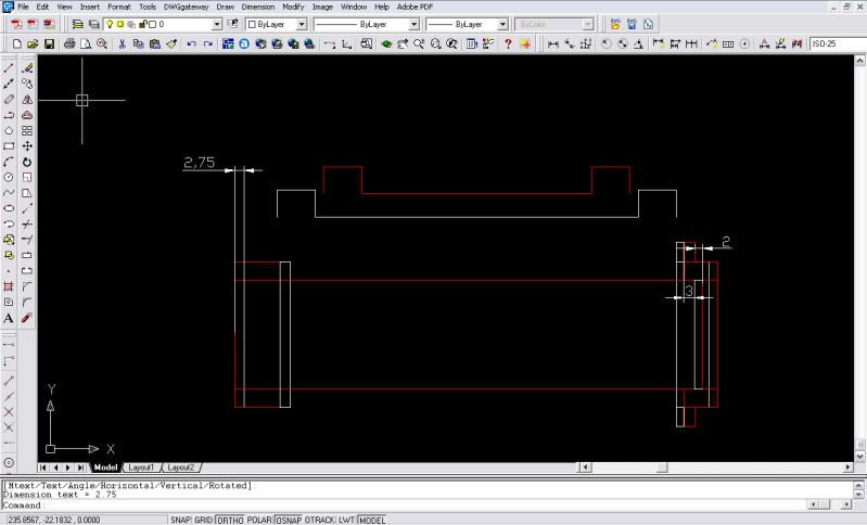
I'd just like to bring everyone back to this CAD drawing....

10001150Wheelrimscentred.jpg


Unless Suzuki originally offset the chain or the wheel rim from the centreline of the bike this is all you need.
When the wheel rims are aligned the bearing face moves by 2.75mm (ish) on one side 2mm (ish) on the other. The "ish" accounts for the missing 0.25mm and being the thickness of two sheets of paper is probably not relevant for our purposes. This assumes that the SPROCKET stays in the SAME place as it always was! (i.e. chain aligned unless Mr Suzuki was stupid).

The ONLY further variable here (if you use the same sprocket hub) is the distance out from the bearing face that the rotor is mounted (that position is set relative to the bearing face by the wheel casting) & might involve playing around with the spacers on that side to get the caliper central above the rotor however the total amount of ADDITIONAL spacer remains the same at 5mm.

This is true for the wheels I have on my shelf... not sure what the rest of you have and yes I know yours are different John, perhaps Joe's matches yours if not mine ;)

All the other CAD drawings are still in this thread. Joe if you want me to email them all & then try to explain them on the phone then I will.

The reason I can say that NO OTHER measurements are important is the Sprocket offset is relevant to the bearing face only & nothing else in isolation - i.e. comparing 2 wheels. This is true only if you use the original sprocket hub & spacer & the original spacer pack on the outside of that.

:)
 
Last edited:
I'd just like to bring everyone back to this CAD drawing....

10001150Wheelrimscentred.jpg


Unless Suzuki originally offset the chain or the wheel rim from the centreline of the bike this is all you need.
When the wheel rims are aligned the bearing face moves by 2.75mm (ish) on one side 2mm (ish) on the other. The "ish" accounts for the missing 0.25mm and being the thickness of two sheets of paper is probably not relevant for our purposes. This assumes that the SPROCKET stays in the SAME place as it always was! (i.e. chain aligned unless Mr Suzuki was stupid).

The ONLY further variable here (if you use the same sprocket hub) is the distance out from the bearing face that the rotor is mounted (that position is set relative to the bearing face by the wheel casting) & might involve playing around with the spacers on that side to get the caliper central above the rotor however the total amount of ADDITIONAL spacer remains the same at 5mm.

This is true for the wheels I have on my shelf... not sure what the rest of you have and yes I know yours are different John, perhaps Joe's matches yours if not mine ;)

All the other CAD drawings are still in this thread. Joe if you want me to email them all & then try to explain them on the phone then I will.

The reason I can say that NO OTHER measurements are important is the Sprocket offset is relevant to the bearing face only & nothing else in isolation - i.e. comparing 2 wheels. This is true only if you use the original sprocket hub & spacer & the original spacer pack on the outside of that.

:)
Did you finally get the 1150 wheel on your bike?
Would you care to share some pictures?
 
I'd just like to bring everyone back to this CAD drawing....

Dan, most of your calculation seem to be about centering the wheel. What counter sprocket offset did you require and how did you achieve it?

I think that is what Joe Nardy was bringing back up which is a 3.5" wheel needing a 4mm offset at the counter sprocket.

And I know that my proposition that counter sprocket offset is primarily a function wheel size might seem counter intuitive when you have been focused on rear sprocket offset relative to wheel centerline. Wheel width would seem to have no bearing on the sprocket offset but infact they have to be related as the wheel has to be designed for a sprocket driven chain to clear the tire that it is driving. So sprocket to cl offset has to increase in direct proportion to wheel width.
 
Last edited:
Dan, most of your calculation seem to be about centering the wheel. What counter sprocket offset did you require and how did you achieve it?

I think that is what Joe Nardy was bringing back up which is a 3.5" wheel needing a 4mm offset at the counter sprocket.

.

You guys are still not getting it... This recipe also centres the sprocket as far as I am concerned.

Let me explain it this way, the bearing face on the sprocket side is connected to the sprocket drive spacer directly. The drive spacer governs where the sprocket sits relative to the bearing face by its length.

Think about this carefully as it's very important.

IF you use the original chain side spacer pack on the outside & the original sprocket hub then the CHAIN LINE MUST BE CORRECT. No offset anything needed!

Now from that point we worry about the rim being central. In my CAD I show that the bearing face is 2.75 too far LEFT (from back) without a spacer which also offsets the Rim by the same amount (with no spacer RIM is offset 2.75mm left viewed from back).
Put that 2.75mm spacer between the bearing face & the rotor spacer to centralise everything.

John - sorry house move has slowed everything down although wheels are coated & just waiting final clearcoat & tyre fitment & then you'll have your pics.... At which point I'll be saying "ner ner" :D or eating a lot of humble pie! One or the other ;) :p
 
You guys are still not getting it... This recipe also centres the sprocket as far as I am concerned.

Let me explain it this way, the bearing face on the sprocket side is connected to the sprocket drive spacer directly. The drive spacer governs where the sprocket sits relative to the bearing face by its length.

Think about this carefully as it's very important.

IF you use the original chain side spacer pack on the outside & the original sprocket hub then the CHAIN LINE MUST BE CORRECT. No offset anything needed!

Now from that point we worry about the rim being central. In my CAD I show that the bearing face is 2.75 too far LEFT (from back) without a spacer which also offsets the Rim by the same amount (with no spacer RIM is offset 2.75mm left viewed from back).
Put that 2.75mm spacer between the bearing face & the rotor spacer to centralise everything.

Dan,
I know you have a pretty thick Brit accent, but I think you just said
"zero counter sprocket offset for a 3.5" wheel"?.
Jim :rolleyes:
 
oh gawd i can't believe i'm here again...
if you don't change the chain side then the drive line stays the same.
the added spacer(s) goes on the rotor side.
i have done dozen or more of these and have had no odd handling or sprocket wear.
street and strip.
daily riders.
the 1150 3.5" rim is narrower in the hub area than an 1100 rim.
**insert beating a dead horse here**
 
Agreed with Blower above however to centre the RIM 2-3mm of the 5mm required needs to go on the left side of the hub (on the left bearing face), the rest on the right.

In practice would a rim offset by 2-3mm to the left make much difference - probably not at our riding level on the street and I doubt it is even very noticeable in practice.

Jim - CORRECT. NO OFFSET ANYTHING REQUIRED TO KEEP THE CHAIN LINE AS SUZUKI INTENDED!

If converting to 530 you will need the standard spacer Z1 supply to go on the OUTSIDE of the countershaft sprocket but that has NOTHING to do with the wheel swap.

Dan :)
 
Agreed with Blower above however to centre the RIM 2-3mm of the 5mm required needs to go on the left side of the hub (on the left bearing face), the rest on the right.

In practice would a rim offset by 2-3mm to the left make much difference - probably not at our riding level on the street and I doubt it is even very noticeable in practice.

Jim - CORRECT. NO OFFSET ANYTHING REQUIRED TO KEEP THE CHAIN LINE AS SUZUKI INTENDED!

If converting to 530 you will need the standard spacer Z1 supply to go on the OUTSIDE of the countershaft sprocket but that has NOTHING to do with the wheel swap.

Dan :)

I attached a plot of the data so far. For the wheels 4" and wider the linear model works pretty well. At 3.5" it appears it could be almost anything depending as there are really no chain clearance issues.


Given the varied results in projecting 3.5" wheels I would guess that you just need to center the rear wheel (Johns magic wheel excepted) and then measure how far your chain is off. You will likely be very pleased to find that the chain alignment is satisfactory as well. Any offsets are probably going to be within a +/- 3mm error bound.

:)

EDIT: Looking at the subsequent posts, the 2-3mm offset required to center the wheel will produce a 2-3 offset requirement on the counter sprocket. The ideal model says you would need 0.125" which is just over 3 mm so very close based on observations.

I also changed the figure as the model looks to work very well. (except for Johns wheel):o
 
Last edited:
Back
Top