• Required reading for all forum users!!!

    Welcome!
    Register to access the full functionality of the GSResources forum. Until you register and activate your account you will not have full forum access, nor will you be able to post or reply to messages.

    A note to new registrants...
    All new forum registrations must be activated via email before you have full access to the forum.

    A Special Note about Email accounts!
    DO NOT SIGN UP USING hotmail, outlook, gmx, sbcglobal, att, bellsouth or email.com. They delete our forum signup emails.

    A note to old forum members...
    I receive numerous requests from people who can no longer log in because their accounts were deleted. As mentioned in the forum FAQ, user accounts are deleted if you haven't logged in for the past 6 months. If you can't log in, then create a new forum account. If you don't get an error message, then check your email account for an activation message. If you get a message stating that the email address is already in use, then your account still exists so follow the instructions in the forum FAQ for resetting your password.

    Have you forgotten your password or have a new email address? Then read the forum FAQ for details on how to reset it.

    Any email requests for "can't log in anymore" problems or "lost my password" problems will be deleted. Read the forum FAQ and follow the instructions there - that's what we have one for...

  • Returning Visitors

    If you are a returning visitor who never received your confirmation email, then odds are your email provider is blockinig emails from our server. The only thing that can be done to get around this is you will have to try creating another forum account using an email address from another domain.

    If you are a returning visitor to the forum and can't log in using your old forum name and password but used to be able to then chances are your account is deleted. Purges of the databases are done regularly. You will have to create a new forum account and you should be all set.

1982 GS850GL gets a (MOSFET) Shindengen FH012AA Rectifier/Regulater

  • Thread starter Thread starter joejeweler
  • Start date Start date
J

joejeweler

Guest
I just got done a few hours ago replacing the original OEM R/R with a R/R out of a 2007 Yamaha,....
...........a Shindengen MOSFET FH012AA,.....just in case! :)

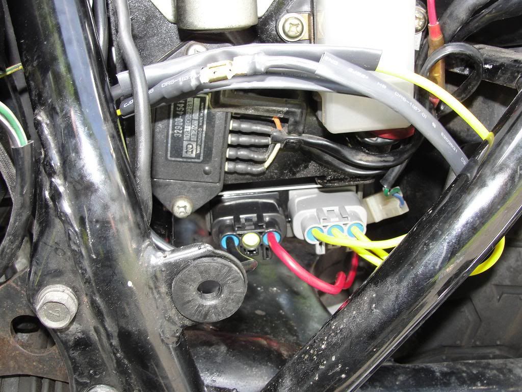
The old R/R was still working 'ok", but given the history of this being a common weak spot on these old girls thought i would get it done today. It took awhile to find one on ebay, and mine looked brand new off a '07 R1 Yamaha bike. Found the 2-connector set (5 wires used here ) in another ebay listing.....

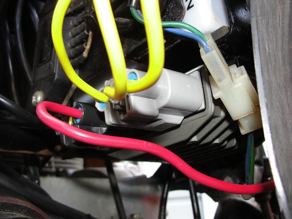
I spent some time last night doing the preliminary wiring and soldering of the connections to both snap connectors. These are some sturdy and sealed connectors!

This site helped a LOT in showing how the wiring goes: http://roadstercycle.com/index.html Jack's video's are really helpful in getting these wired up to the connectors. Once there click on his videos at the top left of the page. 1st video on that link will get you through it just fine!

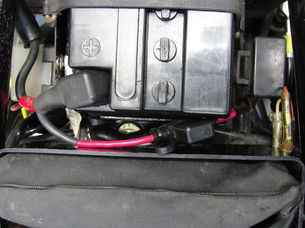
I used 10G wire on both + pos and - neg, and went direct to the battery with both of these.
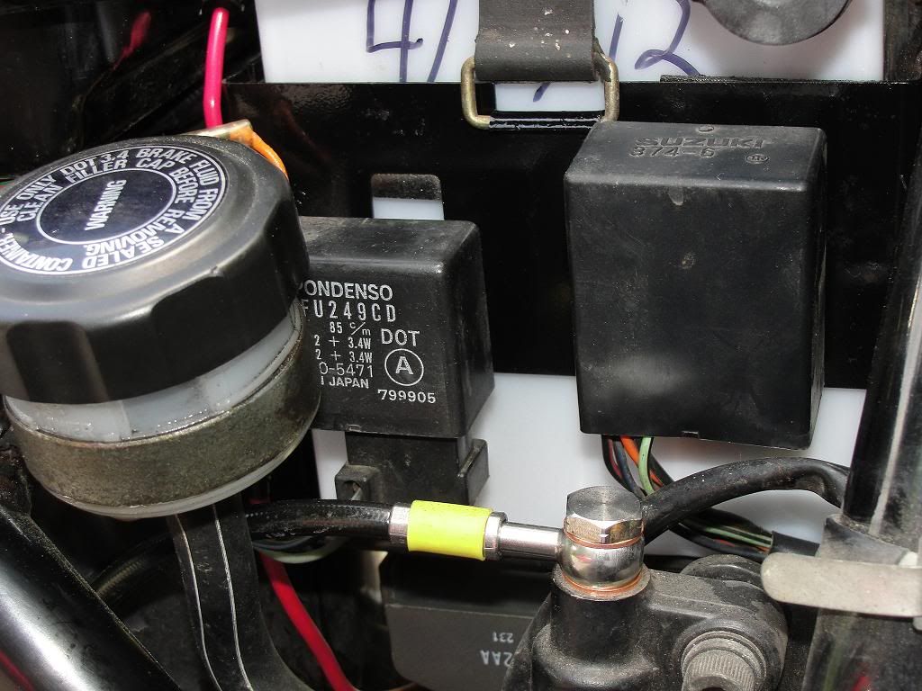
Fitted a 30A "Mini-Fuse" up top on the red (+ pos) wire for easy replacement should the need arise. This fuse can prevent some expensive "smoke",....so don't leave home without it! :D

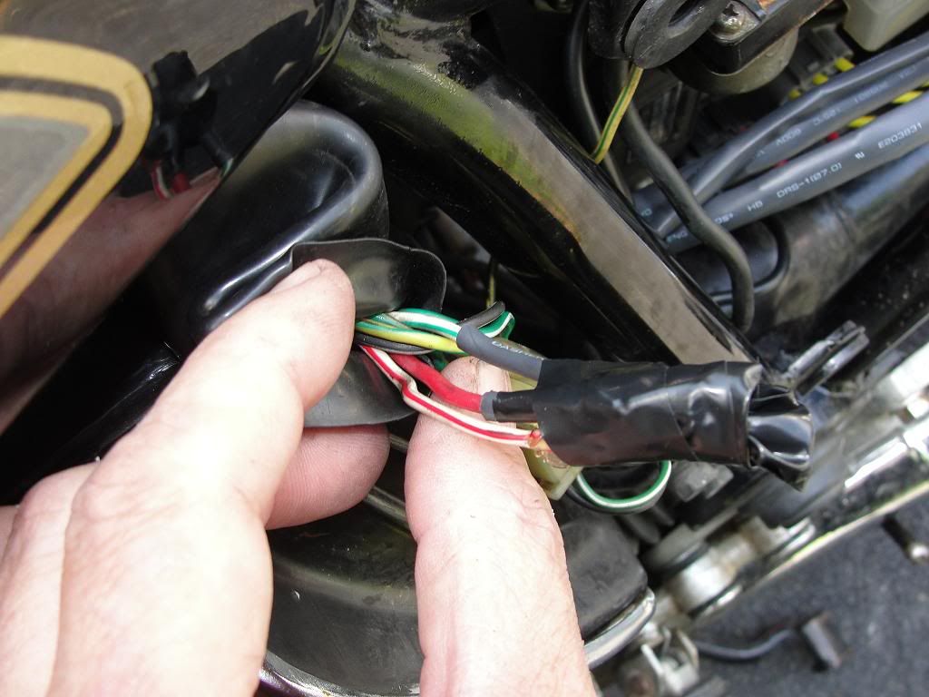
The old (now unused) bullet connectors i used heat shrink tubing on to seal them off, and used some electrical tape to keep them together and out of the way. Just a bit of confusion on the old connection with that oddball wire going into the harness! (up to the headlight area,...:rolleyes: )

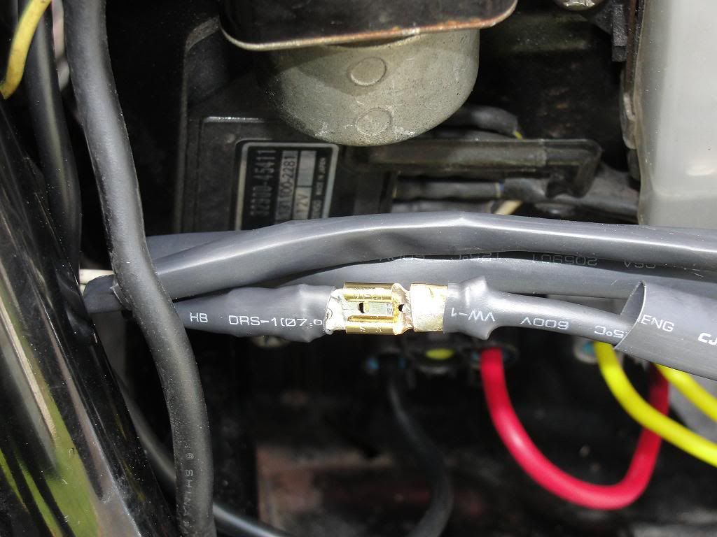
Finally i just traced the wires from where they come out behind the starter,.......cut the bullets off,..... and soldered 3 male spade connectors onto the stator wires, ....and heat shrunk the ends. I folded the thinner stator wires over once before crimping and soldering them right in the garage. Because of their age, i also lightly sanded the wire strands to get some copper showing. After clamping the spade connectors on in 2 places, they soldered up really nice. :)

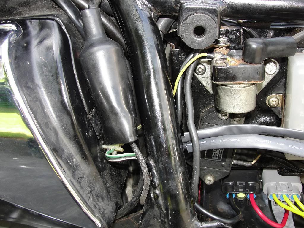
The store was out of the weatherproof type spade connectors, so for now i slid about 8" of heat shring tubing over each wire, and centered each stator connection in the middle. They have a decent friction fit (didn't heat them), but tomorrow i think i'll zip tie all 3 together on either side of the shrink tubing to seal the ends a bit better. Water's not getting in anyway, as the connections are at the top of a gentle curve that leaves each end of the shrink arap about an inch lower. I think i'll leave it this way, and if i ever have to disconnect the stator wires just have to slide the friction fit wrap a few inches either way.


Before i cleaned all my conections several weeks ago, the original OEM R/R was only regulating 12.7 V across the battery terminals. After i cleaned all the conections, it was better,.... getting up to 13.2-13.4 V at about 2K rpm. (2.9 V at idle of 1025 rpm)


The Mosfet FH102AA at an idle of 1025 rpm measures 14.2 V across the battery, and at 2K and higher RPM a pretty stable 14.5 V. :D

My lights are a bit brighter, and the new horn i put on a week ago might wake the neighbors! :eek:

BTW,....This was NOT the simple replacement i read about in BassCliff's experience! http://members.dslextreme.com/users/storagecliff/images/r-r_replacement.pdf

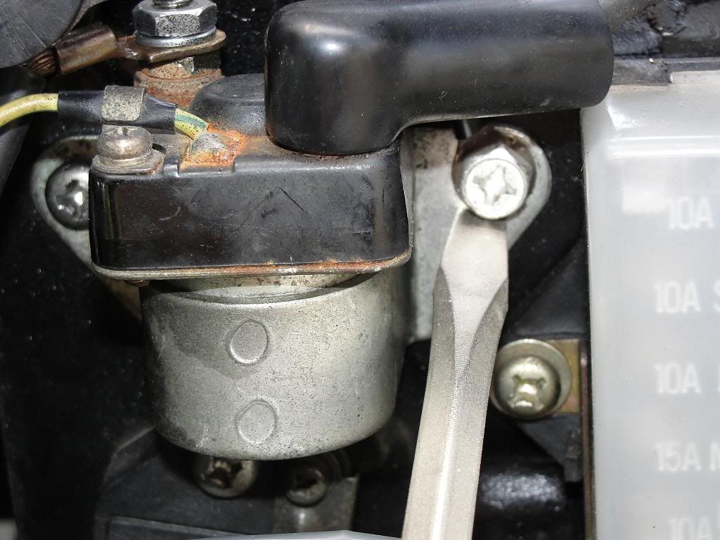
The hardest part was getting the old R/R OUT! Mine was in with frozen phillip's head screws, and not the bolts that Cliff had under his battery box.

Back 6 years ago i had picked up another R/R (shunt type, not a mosfet) from Electrosport as i recall. (still have it) Back then i gave up on the new install,....figuring i'd deal with it if the original broke down. But with all the good things to say about these FH012AA ones,.....i got-er-done today!

The entire battery box had to come out so i could get at the screws holding the R/R on, and i also had one screw that holds the left plate on (outside the battery box and attached to it) that i ended up hand cutting a slot into to allow removal with my gun screwdriver set. It has a rachet handle you can add in addition to the screwdriver handle that gives great leverage with a 5" handle at 90% to the screwdriver blade. Even after a liberal application of chain lube to the screw and an hour wait, it was stubborn.

With the battery box finally out, i had to bring it down to my basement where i still have my jewelry "Foredom" flexshaft machine set up. With a small stone separating disc i carefully cut a slot into the top of each phillips screw. The gun screwdriver setup then was able to remove them.

Since i already had the battery box out, i decided to touch up the paint on it, as they tend to get some surface rust on them after all this time. A light sanding of the worst areas and a scrub down in my sink followed by an air dry from my compressor, and the paint could now get a clean base to stick on. I also touched up on a couple of small frame members in the same area, since they were now accessable. The gloss black rustoleum does a nice job here, and the box was dry and put back in within a few hours.

While the paint was drying i ran out for some longer mounting bolts and washers, and was pleased to find the holes on the battery box were close enough to get it mounted right up! One of the holes in the new R/R has a longer "slot" to the mounting hole,....allowing for some variance in hole spacing.

My battery box hole spacing "just" made it, though...........and i'm really liking my "output"! :cool:

......when i get some time and daylight tomorrow, i'll get a few pics up.
 
Last edited:
Great job! I'd love to see the pictures. I've had mine torn down to do some rewiring and got sidetracked into painting the carbs as well. Now just finding the time to put it back together.

Should be sweet to not worry about the charging system for a while, and eliminate some extra wiring.
 
Good move. I put one on last summer and it's great not to have to think about it. I still have to do the headlight relay mod.
 
First let me say....Love your bike. It's good to see another 82 GL owner. I'm currently rebuilding mine and am diving into installing my Eastern Beaver PC-8 today. As soon as I figure out the correct wiring hook up I'll get her buttoned up.

I just replaced the RR and stator as well. I went with the replacement RR instead of upgrading. I'll save that for another year. :)

Thanks for posting, can't wait to see the pics.
 
Hi Mr. joejeweler,

Good work. Now you're really cooking with electrons! :)


Thank you for your indulgence,

BassCliff
 
I just got done a few hours ago replacing the original OEM R/R with a R/R out of a 2007 Yamaha,....
...........a Shindengen MOSFET FH012AA,.....just in case! :)
...

Back 6 years ago i had picked up another R/R (shunt type, not a mosfet) from Electrosport as i recall. (still have it) ...
Just so you don't disillusion yourself, your new MOSFET regulator is still a shunt-type regulator, it just uses MOSFET-type transistors instead of SCR-types.

Yes the MOSFET is better than the SCR, as it switches quicker and uses less power to transition from ON to OFF, but it's still a shunt-type regulator.

Sorry about that. :o

.

And to add more insult to injury the HONDA SHUNT R/R's with 6 wires have a much better track record than the FH012AA at saving you stator.
 
And to add more insult to injury the HONDA SHUNT R/R's with 6 wires have a much better track record than the FH012AA at saving you stator.

Just so you don't disillusion yourself, your new MOSFET regulator is still a shunt-type regulator, it just uses MOSFET-type transistors instead of SCR-types.

Yes the MOSFET is better than the SCR, as it switches quicker and uses less power to transition from ON to OFF, but it's still a shunt-type regulator.

Sorry about that. :o

.

Well, ....golly,....guess i'll just have to go back to the OEM one then!


......charging at around 13V "gots" to be safer than charging at a steady 14.5V ;)
 
Last edited:
Well, ....golly,....guess i'll just have to go back to the OEM one then!


......charging at around 13V "gots" to be safer than charging at a steady 14.5V ;)

If your shunt r/r is charging the bat at 13.0 volts you have somthing wrong (eg connections) and you are stressing the stator
 
...charging at around 13V "gots" to be safer than charging at a steady 14.5V ;)
If you have an AGM battery (that is construction type, not a brand), they THRIVE on slightly higher voltage.
icon_thumbsup.gif


.
 
.....charging at around 13V "gots" to be safer than charging at a steady 14.5V ;)
Nope, that's hardly charging- go check your car's charging system- most pump 14.5 volts towards battery. It takes about 13.2 volts just to overcome a battery's internal resistance and feed it juice.
 
Joe, the stock charging system is a balance between what the stator is capable of producing and what the bikes 'current' (amperage) needs are. When you installed the MOSFET shunt style regulator, you installed a device that has a voltage drop on one side, not both sides of the full wave portion of the rectifier like the stock unit had. What that means is the unused current is returned to the stator which stresses the stator.

I have a MOSFET R/R on my 80 GS850G...
 
Last edited:
Nope, that's hardly charging- go check your car's charging system- most pump 14.5 volts towards battery. It takes about 13.2 volts just to overcome a battery's internal resistance and feed it juice.

Hehe,....i was joking, sir. Much prefer the 14.5V thank you very much. :)

If your shunt r/r is charging the bat at 13.0 volts you have somthing wrong (eg connections) and you are stressing the stator

I actually measured around 13.4 to 13.5V on the OEM R/R,....but ONLY after i cleaned up a lot of connections.
The FH012AA putting out 14.2V on idle (1025 rpm), and a steady 14.5V from 2000 rpm and higher much better.

Joe, the stock charging system is a balance between what the stator is capable of producing and what the bikes 'current' (amperage) needs are. When you installed the MOSFET shunt style regulator, you installed a device that has a voltage drop on one side, not both sides of the full wave portion of the rectifier like the stock unit had. What that means is the unused current is returned to the stator which stresses the stator.

I have a MOSFET R/R on my 80 GS850G...

I guess i meant to say the FH012AA is a MOSFET type of R/R,....and forgot it is still a shunt type.

The 'FET" part of the "MOSFET" moniker is what really helps to keep these things much cooler than our OEM
ones. ( " Field-Effect Transistor") Cooler is nice!

The entire MOSFET name ("Metal–Oxide–Semiconductor Field-Effect Transistor") just sounds so cool! :cool:

But we have another balance going on here,.....that being a resonable cost/utility/funtion aspect. Unless you're willing
to spend more for a top "series" type R/R,......the MOSFET type is a reasonable choice for these older bikes. Not sure if the series type need a special stator winding either,.....just thinking out loud here?

Now i can ignore the nightmares i was having,......dreaming:

......."Must Fit a MOSFET,.....MUST FIT a MOSFET!" :D
 
Last edited:
OK,...here are some pics i took this morning. I would have prefered to take some before and after
pic to show the bit of rust on the battery box,.....but the camera was in use outside of my reach
and away from home when i was doing the work.

.......but then,.....i guess we ALL know what a little rust looks like on these old girls!

Here is the cleaned up battery compartment, with the "Mini-Fuse" in line on the pos+ lead. I used
a 30A fuse originally, but just changed it to a 15A as i'm thinking it's a bit safer that way. Not sure
why roadstercycle.com uses a 30A auto reset breaker on the pos+ wire in their videos?

SuzukiFH012AARRUpgrade011small.jpg


On the 3 stator wire hookups, i used gold plated spade connectors that i soldered BOTH sides on,
....even the stator wire side. In this case they only had the female side connectors with gold plating.
but i'm sure gold plated male connectors are available.

Because the OEM stator wires were much thinner than the 12G i used
on the R/R side, i folded the wires once to get a good crimp on them, and then soldered.

Before folding the wire ends over on themselves, i lightly sanded the old wires with 220 grit
sandpaper between my fingers. Got some copper showing
for a good solder joint. The un-heated shrink tubing (about 5-6" on each stator wire connection),
serves as a rain guard and is a decent friction fit over the connections. (the store didn't have the
weatherproof type) After the pics the cover was slid back over the connection.

SuzukiFH012AARRUpgrade008small.jpg


....an overall view of the install. (sheath to cover spade connection still not slid back)


SuzukiFH012AARRUpgrade007small.jpg


Here the protective slide cover back over the connection. I used dielectric grease to protect the connections from oxidation under the pulled over shring wrap, since the ends aren't sealed. Easy to get at the connections should the need arise.

SuzukiFH012AARRUpgrade002small.jpg


If you have phillips screws holding your OEM R/R onto the bottom of your battery box, i guarantee
you'll have to remove your battery box like i did to get the old R/R off!

This screw on the right side i had to hand saw a slot into, in order to get this entire side plate off.
(so you don't have to remove the electrical parts individually)

It is the screw i'm pointing at with a large flat screwdriver blade. The new screw/bolt combination is
one i had from an old battery connection,.....but any 6 sided bold will work fine.

Avoid the phillips screws,....a real PITA to get off usually!

You can see the other original phillips head on the left side of the starting solinoid,...still frozen but if
the solinoid needs replacing i'll deal with it then.

SuzukiFH012AARRUpgrade009small.jpg


The 2 rectangular shaped componants under the right side cover just lift off that side of the battery box:

SuzukiFH012AARRUpgrade013small.jpg


An overall view of the unit installed:

SuzukiFH012AARRUpgrade020small.jpg


I pulled the red wire down a bit to better show the nice plugs on this unit.....well sealed with the rubber
plugs the wires go through.

......closer view,....really like the removable connections on this FH012AA R/R, and it's NOW mounted
with 6 sided bolts to allow easy removal without having to tear out the battery box next time.


SuzukiFH012AARRUpgrade014small.jpg


This is where some of the original stator wires connected under the left side cover.....i used heat shrink
tubing on the 2 male bullet connectors, .....the female connector was already protected with it's vinyl
cover. Then used electrical tape to keep them separate. Others will know these are no longer being used.
(especially the crap routing to the headlight area!)

SuzukiFH012AARRUpgrade022small.jpg


.....and here neatly covered back up with the OEM rubber wire bundle sheath:

SuzukiFH012AARRUpgrade024small.jpg
 
Last edited:
BTW,....thought i would show a few pics of the new HEL SS brake line hoses i installed
a few weeks ago up front. (back line done 2 days ago also)

I had the 3 piece set for the front made with plain SS banjos, with a black outer covering to
match everything else. D

I didn't want a flashy red or other color for the hoses,.......

.......after all,.....she IS a respectable older LADY! :rolleyes:

SuzukiFH012AARRUpgrade030small.jpg


Do yourself a favor and pick up a set of stainless steel "Speed Bleaders"! These have a brass inner core, but the main body is SS.
Makes short work of getting the fluids replaced, and come with a thread sealant already installed. (no chance for air to get in along the threads!)

.......best $13 i've ever spent for each nipple! ;)

Over the winter looks like a touchup to the paint on the calipers might be in order! :o

I'm not sure how they might look stripped of all paint either,....but might make sense for this area! :D

SuzukiFH012AARRUpgrade028small.jpg


Here you can make out the connection of the rear HEL SS brake line at the master cylinder,....along the bottom.
The HEL rear brake line was much shoter than the original rubber one, but made for a more sensible connection.

The original OEM rubber hose went right past the rear master cylinder, then up and back around to connect pointing
to the rear of the bike. Not only wasted length, but i HAD to cut the original hose in order to get it off.
The hose went through a solid metal opening on the swing arm that the banjo had NO chance to fit through!

.....how in the world was the average home mechanic supposed to replace the rear hose at the recommended
2 year interval, when at least one banjo has to be fitted AFTER the hose is layed out along the original route?

SuzukiFH012AARRUpgrade013small.jpg
 
Last edited:
... how in the world was the average home mechanic supposed to replace the rear hose at the recommended 2 year interval, when at least one banjo has to be fitted AFTER the hose is layed out along the original route?
I have not replaced the hose, but I have had it fully removed from the bike with no problems.

I presume you are referring to the loops that hold the hose to the swingarm? They are only attached on one side. Lift the other side slide the hose in, tap the retainer loops back down with a hammer.

.
 
My current bike has a Compufire as recommended by Pos/Jim, but I've installed a few of these FET type R/R's and recommend them over the other shunt alternatives. Didn't feel like paying for those fancy connectors, although they are very nice, so the wires were attached with naked spade terminals and then the cavity was filled with MIL-SPEC grade silicone sealer that doesn't attack electrics (no acid). Looks a bit getto but works well.

IMG_1320.jpg


Hehe,.....the "fancy" connectors were $22.95 on ebay,....not cheap, but then the silicone sealer can get costly too, but i'm thinking you already had some lying around. :)

BTW,....surprised you used phillip head screws with the new R/R mount up???

After all the trouble i had getting the 30 year old stock screws loose, the replacement 6 sided bolts i used will save me some aggravation should i ever need to take the R/R out. (as will the matching "pull-off" connectors! ;) )

Spade connectors just as effective, but i guess had the matching connectors not been available i would have turned down some water faucet washers to fit each wire hole. The 10g and 12g wires i used pretty close to filling the normally used center screw hole. Then a pop in/off fit. :D

Edited to add: Oops,...just noticed you mounted it on the side, and not on the bottom of the battery box like the original. So the screws are accessable at least. Bolts or allen heads still my 1st choice on any replacements, however.
 
Last edited:
Back
Top