N
Nicholaschase29
Guest
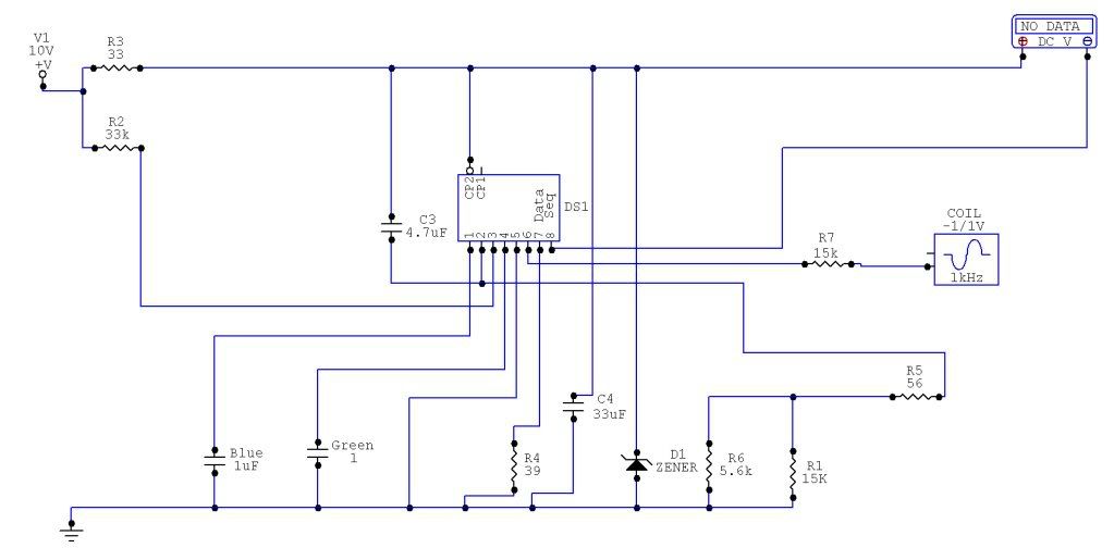
I havent had the time to read this whole thing, but my 1100ESD tach is somewhat sketchy at times. Especially it seems when its cold out. At the same speed/throttle position in the same gear it will read at times as much as 6k RPM or as little as 3.5K RPM. It seems less likely to do this when warm, and i have a spare tach unit at my disposal, but id really like to know HOW this thing works, as the shop manual says NOTHING about it, so that in the future i can know HOW to fix a faulty one.
Some advice, when you do disassemble the gauge cluster the odometer reset knob does not pull off. I tried pulling up on the plexiglass case and cracked it
 . You need to take the screws out of the white plastic backing that hold the tach and speedo, then pull the white plastic away from the face. If you want to pull the plexiglass off you need to pull the back away then the knob is held on by a clip and a cotter pin.
Confusing I know, but if you look on bikebandit you'll see what i mean. I just want to save you the $60 mistake I made breaking the gauge glass.
") Actually to be fair, it's a restoration that's going to be a wedding present, so I have no idea what works and what doesn't until I go over the entire bike.
Actually to be fair, it's a restoration that's going to be a wedding present, so I have no idea what works and what doesn't until I go over the entire bike.