• Required reading for all forum users!!!

    Welcome!
    Register to access the full functionality of the GSResources forum. Until you register and activate your account you will not have full forum access, nor will you be able to post or reply to messages.

    A note to new registrants...
    All new forum registrations must be activated via email before you have full access to the forum.

    A Special Note about Email accounts!
    DO NOT SIGN UP USING hotmail, outlook, gmx, sbcglobal, att, bellsouth or email.com. They delete our forum signup emails.

    A note to old forum members...
    I receive numerous requests from people who can no longer log in because their accounts were deleted. As mentioned in the forum FAQ, user accounts are deleted if you haven't logged in for the past 6 months. If you can't log in, then create a new forum account. If you don't get an error message, then check your email account for an activation message. If you get a message stating that the email address is already in use, then your account still exists so follow the instructions in the forum FAQ for resetting your password.

    Have you forgotten your password or have a new email address? Then read the forum FAQ for details on how to reset it.

    Any email requests for "can't log in anymore" problems or "lost my password" problems will be deleted. Read the forum FAQ and follow the instructions there - that's what we have one for...

  • Returning Visitors

    If you are a returning visitor who never received your confirmation email, then odds are your email provider is blockinig emails from our server. The only thing that can be done to get around this is you will have to try creating another forum account using an email address from another domain.

    If you are a returning visitor to the forum and can't log in using your old forum name and password but used to be able to then chances are your account is deleted. Purges of the databases are done regularly. You will have to create a new forum account and you should be all set.

1st generation AUTO cancel TSCU "banging the bits"

Status
Not open for further replies.

rustybronco

Forum Guru
Past Site Supporter
TGSR Superstar
Past Bard Award Winner
Has begun...


(I still haven't decided what to do with the serial in/out pins yet. It's either tie them to 0V or connect them a 3.5mm jack so the Picaxe can be programmed in place.)

How it works

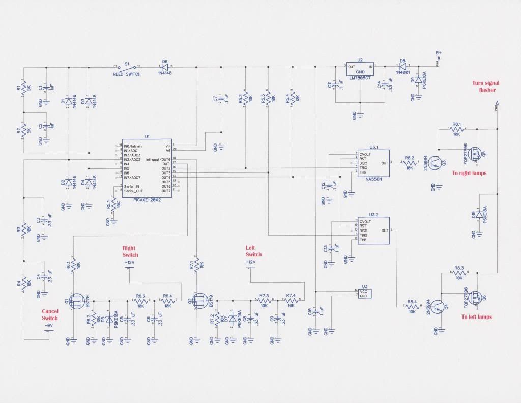
The combination of R1-R2-C1-C2 form a 2nd order low pass filter which attenuates (reduces) frequencies above 338'ish Hz. (design centers around a maximum reed switch frequency of 290 Hz @120 Mph)

D6 is a voltage 'dropping' diode which lowers the supply voltage (5.0V) by .4 or so volts (it all depends on the amount of current flowing).

D3-D4 are used as transient suppressors. (can't have static destroying components can we!) When the reed switch in the speedometer is closed, diodes D3 and D4 conduct whenever the voltage tries to go over 5.0V OR below -.4V (current flows in a loop) When the reed switch is open those same diodes conduct at approximately .4V OR -.4V (Rail voltage 4.6V OR .0V depending on if the reed switch is open or closed)

R3-R4-C3-C4 are 2nd order low pass filters for the cancel circuit (there are low pass filters at the input of Q1 and Q2 as well), keeping 'noise' from false triggering the Right, Left and Cancel circuits.
(hey! I didn't push that switch, why are the turn signals on?) D1 and D2 are the transient suppressors for the cancel circuit.

U1 is the microcontroller (?C) that takes the input from the reed switch, right, left and cancel switches and uses those inputs to pull either the reset (RST) or trigger (TRIG) lines of U3 low (near 0 Volts) turning on or off the signals.

U3 (U3.1-2-3) is a bi-stable flip flop (stable in the 'on or off' condition until triggered in the opposite state)

Q3 and Q5 (Q4-Q6 also) are nothing more than an electronic relay allowing current to flow from turn signal flasher to the turn signals.

U2 is a 5 volt regulator which powers the device.

D8 is to protect from a battery being connected backwards.

D5-D7-D9-D10 are also transient suppressors to protect their associated circuits.

*******

A BIG thanks to Duanage for his help getting this portion of the project started and to Robert Barr and Wallogreen (Martin) for their input and help as well.

'Banging the bits' software design in progress.

Wish me luck!


EDIT*** Uploaded latest iteration 05-17-14
 
Last edited:
Actually its pretty simple if you look at it in stages.

You have a device, the NA556, which is a dual 555 timer in one package configured as a bi-stable flip-flop (stable either in the on or off state). When you apply a voltage, 5 volts in this case to either trigger pin, the NA556 outputs a voltage to the 2N3904 that is kept turned on until it is turned off by pulling the RST line low, which in turn pulls the 'gate' of either FQP27P06 Mosfet low (near 0V), turning on the Mosfet ( held high (off) by R7.1 and R7.3), allowing current to flow from flasher to signal lamps.

R7.2 and R7.4 are in place to limit the current going to the 2N3904. Those two devices, the 2N3904 and FQP27P06, in the way they are paired up, are nothing more than an 'electrically' operated light switch used to turn your house lights on and off.

Most of the diodes are in place to protect all the inputs from Electro Static Discharge (ESD).

The lone exception, D8, near the LM7805 (a 5 volt regulator), is in place to keep the whole mess from frying if someone connects the battery up backwards. ;)


The BS170's, also Mosfets, are in place so you can use the 12 volts coming from the right and left turn signal switches without cooking the ?Controller as it can only handle a maximum of 5.5 volts on it's inputs. Go to 5.6 volts and it will fry.

The Picaxe (20X2) was selected for it's internal timer, two 'hardware interrupts', and because the dummy trying to write the code MAY have a chance at making it all work.

It's not like I've ever done this before... :D
 
Last edited:
It's cheating to read the directions. You realize this?

I look forward to seeing the physical result. Mine's pretty primitive, with no attractive-looking PCB. Never did figure out a reasonable way to provide strain relief for a harness / board interface.
 
It's cheating to read the directions. You realize this?
It is? Now you go and tell me!

Mine's pretty primitive, with no attractive-looking PCB. Never did figure out a reasonable way to provide strain relief for a harness / board interface.
Well there is always eagle cad or diptrace to start you on the path to a professional looking PCB from OSHpark. Shouldn't be to hard with the low parts count your design has.

http://oshpark.com/
 
RB, did you mention you'd mocked up the first circuit (the one you sent me) without the uP? If so did you try hooking it into a bike and testing it with the engine running?

At the expense of throwing a damper on things, it'd be nice to know how that worked out...
 
Martin, I did breadboard it up but I don't have a working bike to test it out on. I guess I could run three wires under the fuel tank of the 80 GS850 and see what it does under those conditions or, I could get my butt in gear and finish the '78.

I'm waiting on the TVS diodes. Maybe I'll connect it up as soon as those arrive.
Don't know if that's a proper test or not because of the jumpers on the breadboard. ??

Making the engine stand for it this week! :)
 
Last edited:
Are you using the BASIC software development tool or the graphical flow charting tool to write the software?
 
I had a note cross the local hackerspace mailing list about a guy doing small-batch circuitboards online at circuitboards.com

If enough people are interested in (and can agree upon) a board solution, apparently you can get that guys to make you a few. I havn't checked out his site yet, so proceed with caution.
 
JTGS850GL, Neither.

I'm roughly figuring out all the steps necessary to implement the different functions and going through all the Basic commands trying to make it all work without having to make the processor wait for an unreasonable amount of time, and cover all the inputs and flags. Basically I've got a bunch of sheets with all the goto gosub interupts timer3 etc printed out and sitting down with them until I can understand how to put all the different 'calls and functions' together.

I've got to understand it first.
 
Last edited:
Martin, I did breadboard it up but I don't have working bike to test it out on. I guess I could run three wires under the fuel tank of the 80 GS850 and see what it does under those conditions or, I could get my butt in gear and finish the '78.

I'm waiting on the TVS diodes. Maybe I'll connect it up as soon as those arrive.
Don't know if that's a proper test or not because of the jumpers on the breadboard. ??

Making the engine stand for it this week! :)

Well from the experience with my effort, don't forget my design around the inputs changed drastically when I connected it in to the bike after working flawlessly on the bench. All because of the environment the thing has to work in. Not sure what the noise immunity is going to be like with your input configuration but be wary it's likely to need some help there to eliminate false detection.
 
Στην πραγματικότητα αρκετά απλή του , αν το δει κανείς σε στάδια .

Έχετε μια συσκευή , η NA556 , η οποία είναι μια διπλή 555 χρονόμετρο σε ένα πακέτο διαμορφώνεται ως bi - σταθερή flip- flop ( σταθερό είτε σε εντός ή εκτός του κράτους ) . Όταν εφαρμόζετε μια τάση , 5 βολτ σε αυτή την περίπτωση είτε να pin ενεργοποίησης, η NA556 εξάγει μία τάση προς το 2N3904 που παραμένει ενεργοποιημένος μέχρι να απενεργοποιηθεί από το τράβηγμα της γραμμής RST χαμηλά , η οποία με τη σειρά της έλκει την ?πύλη? του είτε FQP27P06 Mosfet χαμηλή (κοντά 0V ) , την ενεργοποίηση του Mosfet ( ψηλά ( εκτός) από R7.1 και R7.3 ) , που επιτρέπει τη ροή ρεύματος από το καζανάκι για να επισημάνει τους λαμπτήρες .

R7.2 και R7.4 είναι σε θέση να περιορίσει το ρεύμα πηγαίνει στο 2N3904 . Οι δύο αυτές συσκευές , η 2N3904 και FQP27P06 , με τον τρόπο που δούλεψαν μαζί , δεν είναι τίποτα περισσότερο από ένα ελαφρύ διακόπτη ? ηλεκτρικά ? λειτουργία χρησιμοποιείται για να μετατρέψει τα φώτα του σπιτιού σας και να σβήνουν .

Οι περισσότερες από τις διόδους είναι σε θέση να προστατεύσει όλες τις εισόδους από Electro Static Απαλλαγή ( ESD ) .

Η μοναδική εξαίρεση , D7 , κοντά στο LM7805 ( ρυθμιστής 5 volt ) , είναι σε θέση να κρατήσει ολόκληρο το χάος από το τηγάνισμα , αν κάποιος συνδέει την μπαταρία μέχρι πίσω .

Το BS170 του , επίσης Mosfets , είναι στη θέση τους , ώστε να μπορείτε να χρησιμοποιήσετε τα 12 βολτ που προέρχονται από τα δεξιά και αριστερά διακόπτες φλας χωρίς μαγείρεμα το μController , δεδομένου ότι μπορεί να χειριστεί μόνο ένα μέγιστο των 5,5 βολτ για τις εισόδους του . Πηγαίνετε στο 5,6 βολτ και θα τηγανίζουμε .

Η Picaxe ( 20Χ2) επιλέχθηκε για αυτό είναι εσωτερικό χρονόμετρο , δύο ? διακόπτει υλικού ? , και επειδή το ομοίωμα προσπαθεί να γράψει τον κώδικα μπορεί να έχει μια ευκαιρία να κάνει όλες τις εργασίες .

Δεν είναι σαν να έχω κάνει ποτέ αυτό ...

Means about the same to me.
dontknow.gif
dontknow.gif

But I know it will work and work well.
thumbsup.gif
 
Not sure what the noise immunity is going to be like with your input configuration but be wary it's likely to need some help there to eliminate false detection.
I figured there might be an issue with the inputs, especially the cancel line as it's not isolated like the Right and Left inputs are. Not saying those won't wont be without issue either. :D

Might need to take a look at your design in the future If I have an issue I can't easily over come. Trying to do this with as little input as I can...
 
Last edited:
Am I not looking at this right or are your Left and Right switch's wired into output lines? Or is the bus on the 20M2 bidirectional?

Edit: Never mind... I just verified that the 20M2's bus is programmably bidirectional
 
Last edited:
Am I not looking at this right or are your Left and Right switch's wired into output lines or is the bus on the 20M2 bidirectional?
The schematic shows a 20M2 pinout. I edited the pin configuration in diptrace using their component editor but I couldn't find a way to incorporate the new part into my diagram. Guess I should read the manual someday. :) Not to worry, the 20M2 and 20X2 are pin for pin compatible. The only difference is the pin nomenclature.

Here's the pinout for the 20X2... www.picaxe.com/docs/picaxex2.pdf

Almost all of the pins are configurable as either an input, output or (??).

Picaxe 20M2 for comparisons sake. www.picaxe.com/docs/picaxem2.pdf
 
Last edited:
Means about the same to me.
dontknow.gif
dontknow.gif

But I know it will work and work well.
thumbsup.gif

I think its written in Murrican ? :confused: I'm so confused I'm going to go out in the sunshine for a ride and contemplate my indignation......
 
And may an electronically challenged Goose lay a nice big solenoid on your clean-dry windscreen while you do. :D
 
And may an electronically challenged Goose lay a nice big solenoid on your clean-dry windscreen while you do. :D

Never mind the TSCU. Figure out how I can put an air conditioner on the bike ? :confused: { nice comeback by the way } :D
 
I had a note cross the local hackerspace mailing list about a guy doing small-batch circuitboards online at circuitboards.com

If enough people are interested in (and can agree upon) a board solution, apparently you can get that guys to make you a few. I havn't checked out his site yet, so proceed with caution.
Thanks for the heads up! I plan on using OSHpark's board service when this project gets that far.

https://oshpark.com/
 
Status
Not open for further replies.
Back
Top