• Required reading for all forum users!!!

    Welcome!
    Register to access the full functionality of the GSResources forum. Until you register and activate your account you will not have full forum access, nor will you be able to post or reply to messages.

    A note to new registrants...
    All new forum registrations must be activated via email before you have full access to the forum.

    A Special Note about Email accounts!
    DO NOT SIGN UP USING hotmail, outlook, gmx, sbcglobal, att, bellsouth or email.com. They delete our forum signup emails.

    A note to old forum members...
    I receive numerous requests from people who can no longer log in because their accounts were deleted. As mentioned in the forum FAQ, user accounts are deleted if you haven't logged in for the past 6 months. If you can't log in, then create a new forum account. If you don't get an error message, then check your email account for an activation message. If you get a message stating that the email address is already in use, then your account still exists so follow the instructions in the forum FAQ for resetting your password.

    Have you forgotten your password or have a new email address? Then read the forum FAQ for details on how to reset it.

    Any email requests for "can't log in anymore" problems or "lost my password" problems will be deleted. Read the forum FAQ and follow the instructions there - that's what we have one for...

  • Returning Visitors

    If you are a returning visitor who never received your confirmation email, then odds are your email provider is blockinig emails from our server. The only thing that can be done to get around this is you will have to try creating another forum account using an email address from another domain.

    If you are a returning visitor to the forum and can't log in using your old forum name and password but used to be able to then chances are your account is deleted. Purges of the databases are done regularly. You will have to create a new forum account and you should be all set.

79 550 Cafe-"ish" Build

8ball

Forum Mentor
I picked up a winter project GS550, and have been lurking around here for a few months. I have been keeping a running build thread on another forum, but figured I probably should post it here, as well.

A little bit about me: I have been riding motorcycles for over 30 years. My first street bike was a 1973 CB500F that I always wished I had the money to build into a cafe racer....but as a college student, that didn't happen. Later I got a CBR600 and quickly found a new addiction to the track, which had me racing for about 12 years (CBR600, CBR600F2 and FZR400's). I currently own a 2003 R6, an XR400 that I made my own dual sport kit for, a V-Star....and this 1979 GS550 project.

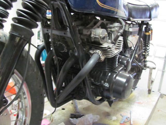
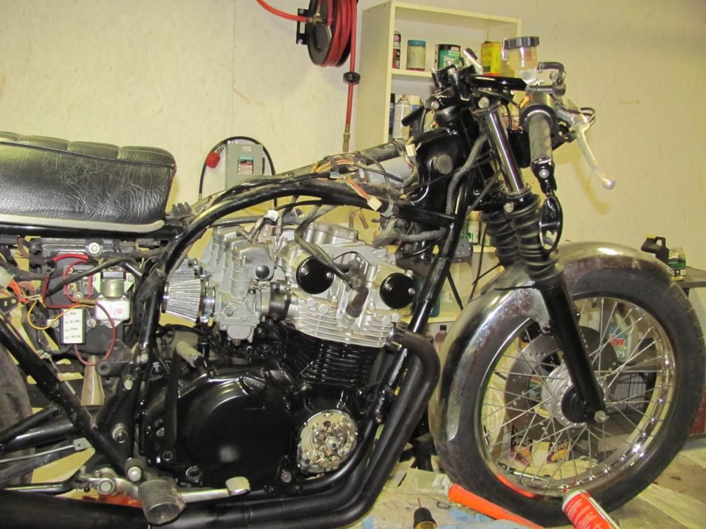
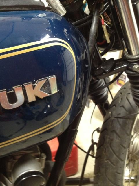
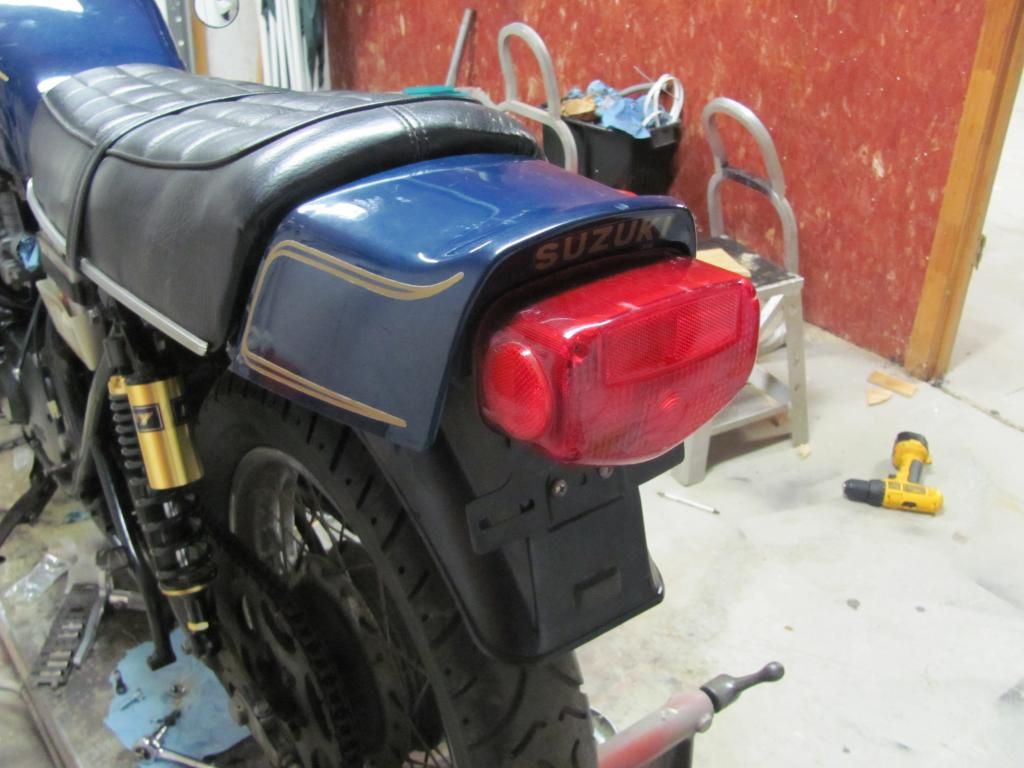
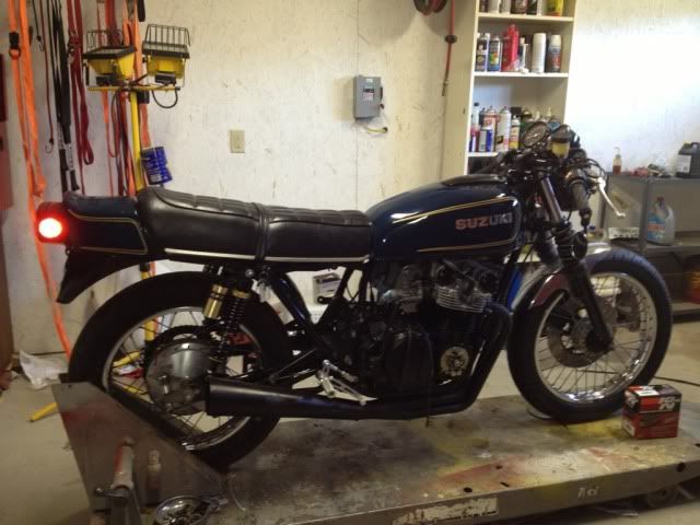
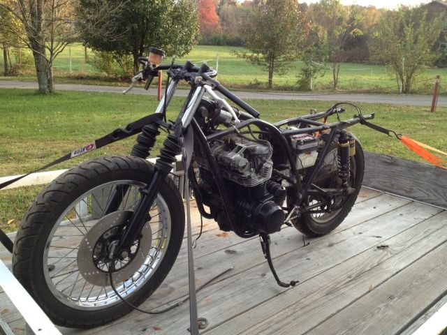
A friend of mine bought the bike and started a Cafe Racer build on it, then ran out of time and room. Here's what it looked like when he got it a few months ago:
index.php


It was in fairly good shape, and actually ran (however not so well), which was surprising since it had been stored for quite a while. He started stripping and cleaning and picked up a few mod parts (Dyna ignition, clubman bars, larger carbs, exhaust, etc....). Then he ran out of time and room in his garageand I ended up with it for $600.

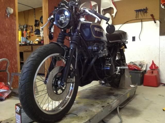
Here is how I brought it home:

E6347A53-C94C-4E3F-9453-C240E79097E8-6180-000008FD4C4490D9.jpg

E3773998-9B05-477A-BCA5-F73097CCA9B5-6180-000008FD438F3CAC.jpg

3FF17B78-02CF-465F-B4E6-505CFF3FAAF3-6180-000008FD39E64DBA.jpg


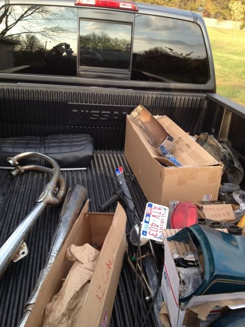
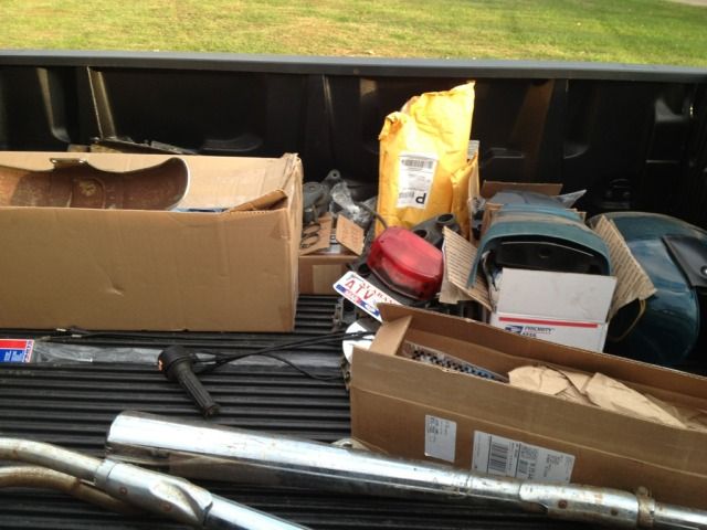
Here's a list of parts that were in the pile:

-All of the stock parts
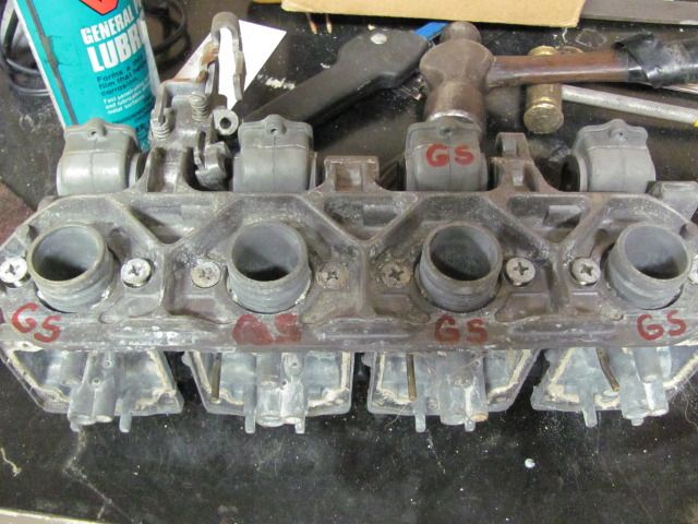
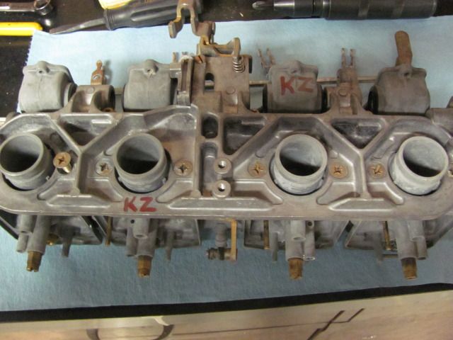
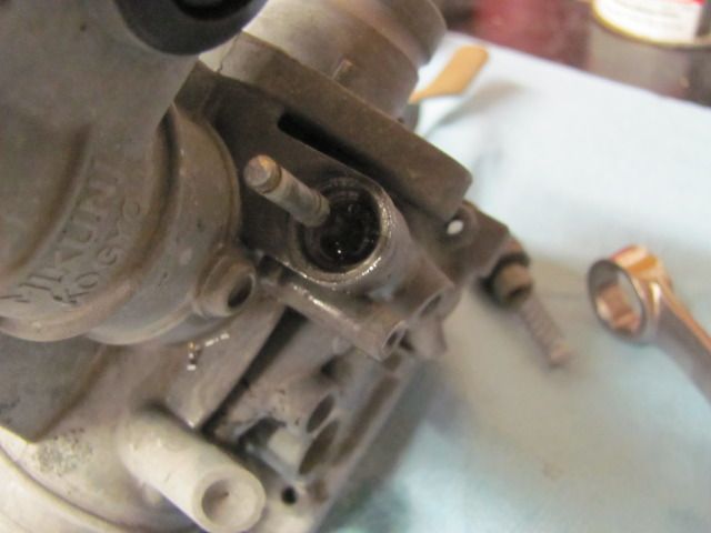
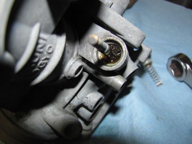
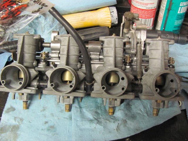
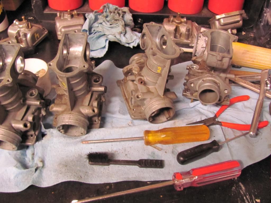
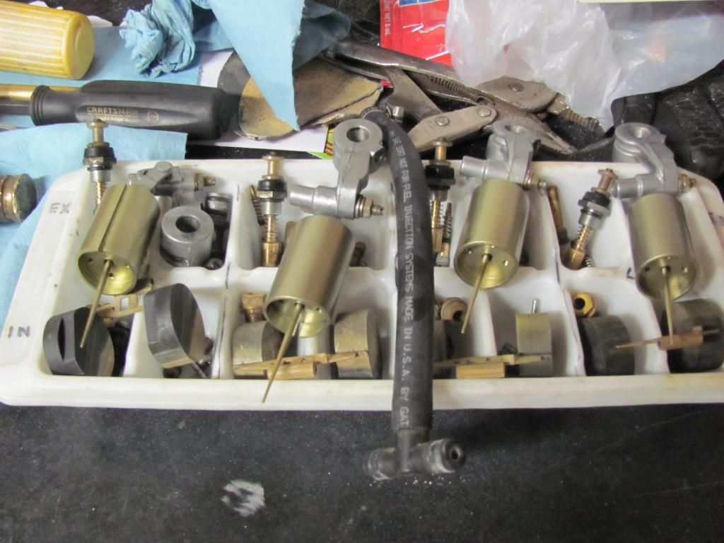
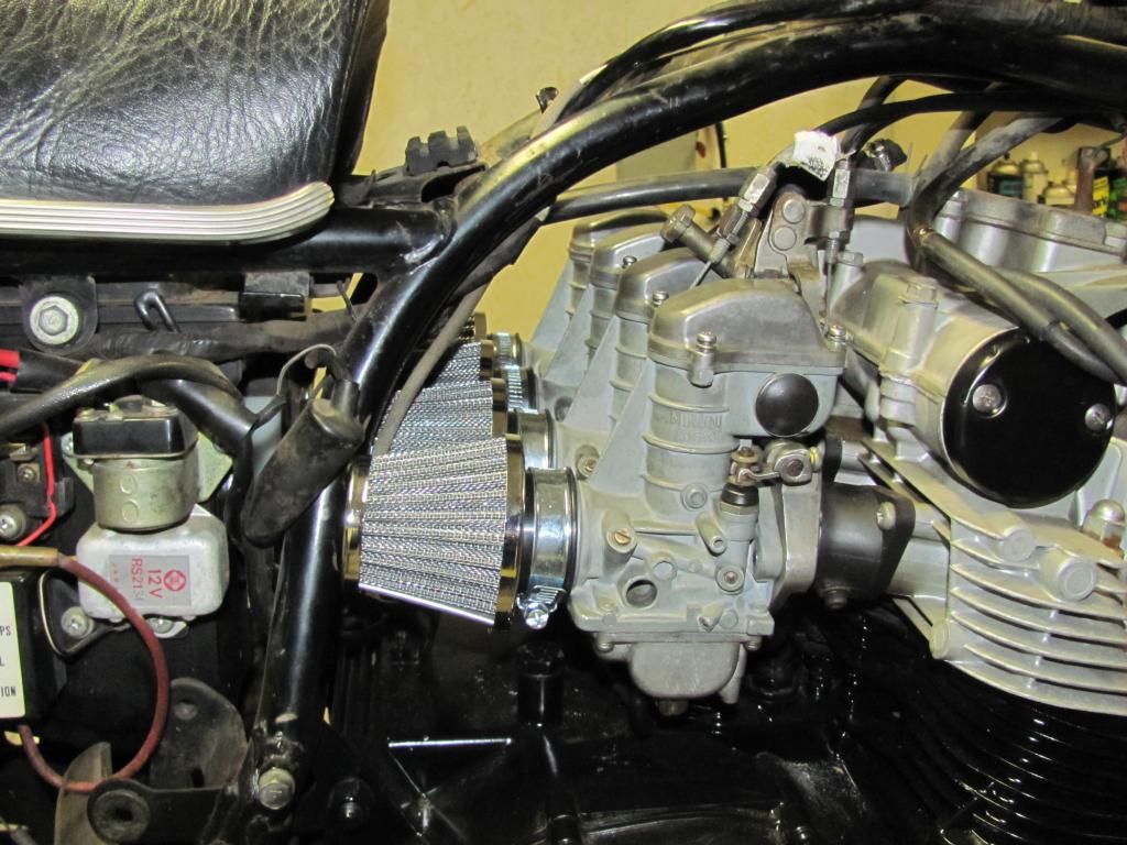
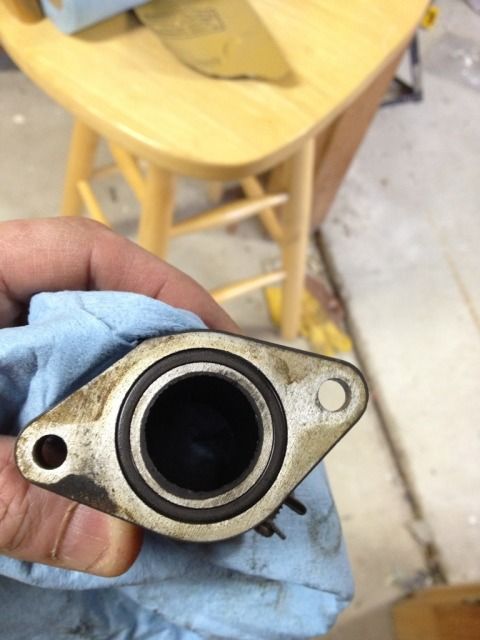
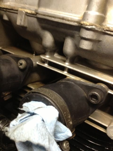
-The bike actually ran, but the carbs are pretty messed up, so there is a set of 2mm larger KZ carbs that I plan to re-rack on the GS rack. (Yes I am capable of extensive carburetor work). Other parts that came in the pile:
-Clubman bars
-new Dyna electronic ignition system (with coils)
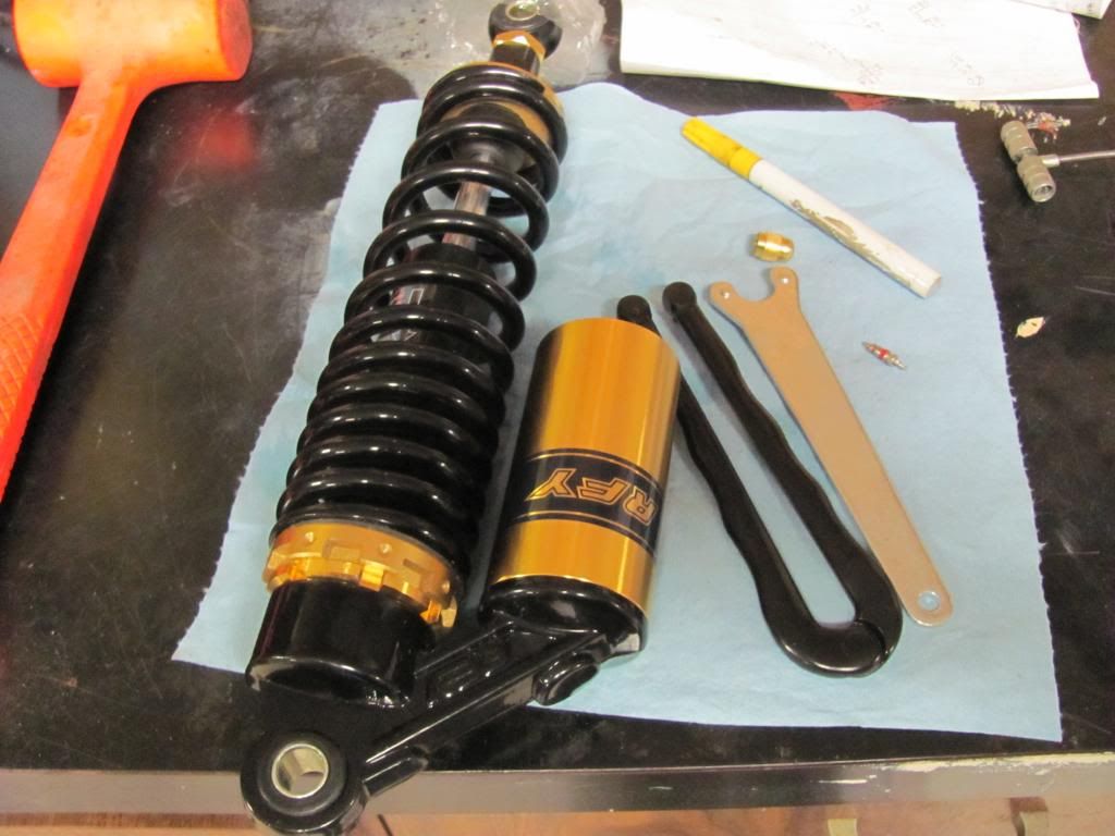
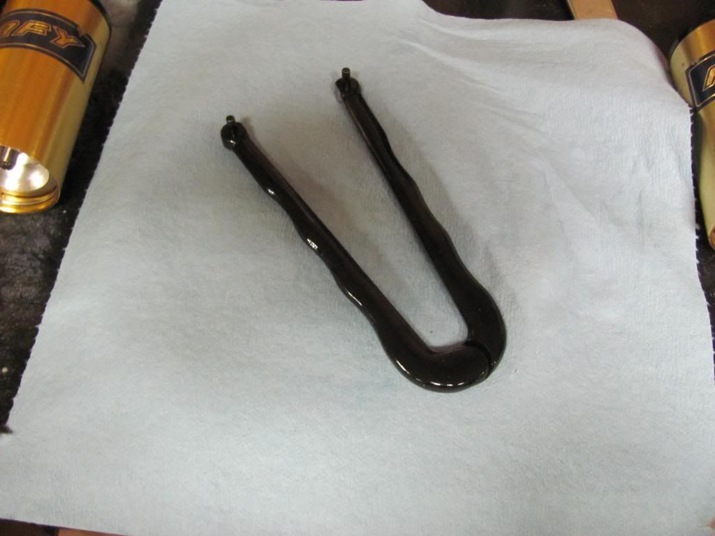
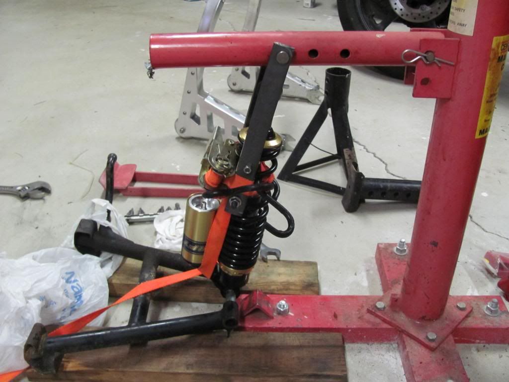
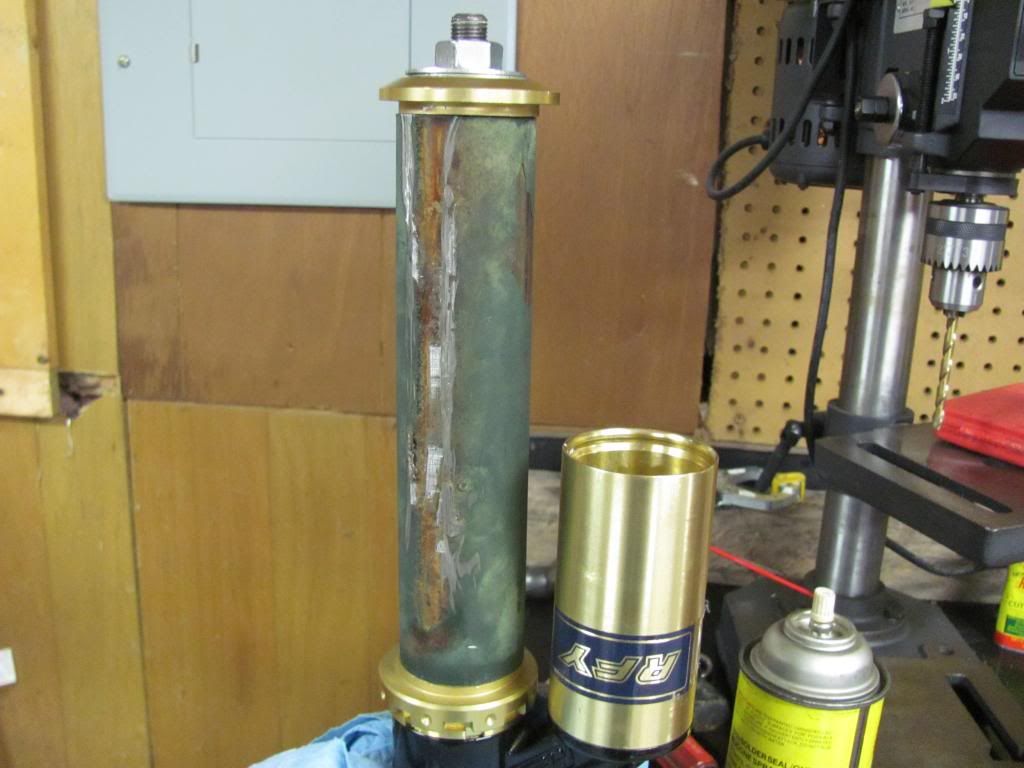
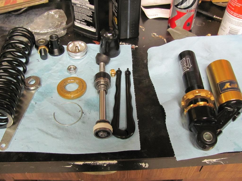
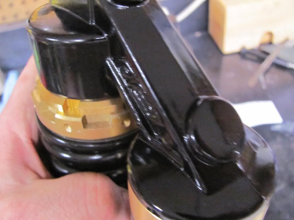
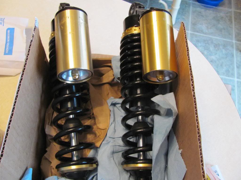
-KFY Chinese knock-off shocks (cheap I know, but I will see how they work)
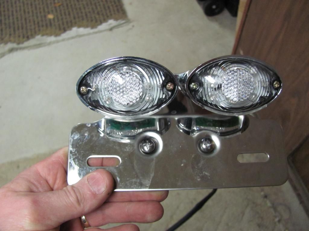
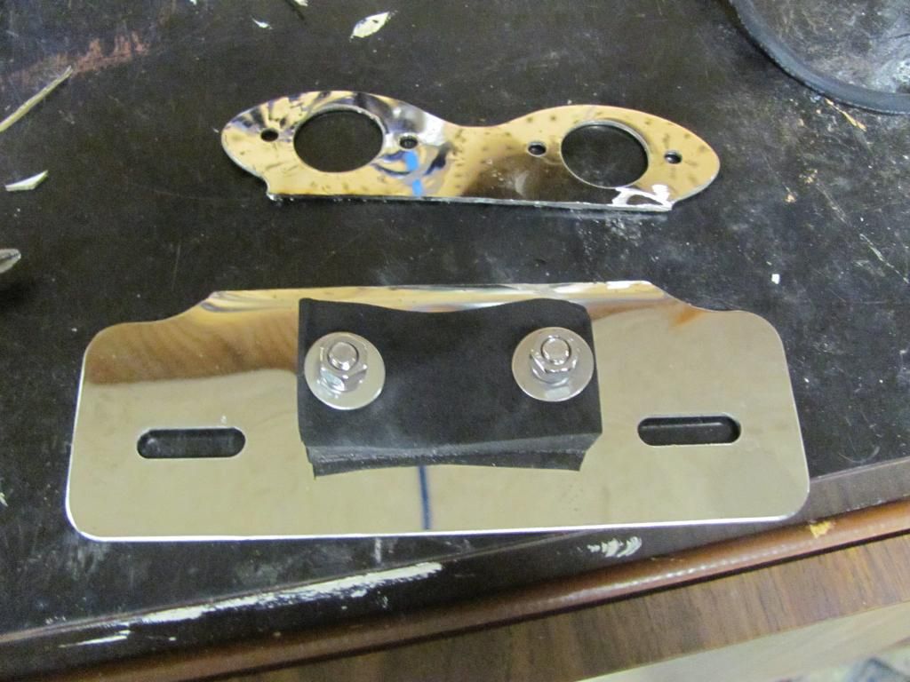
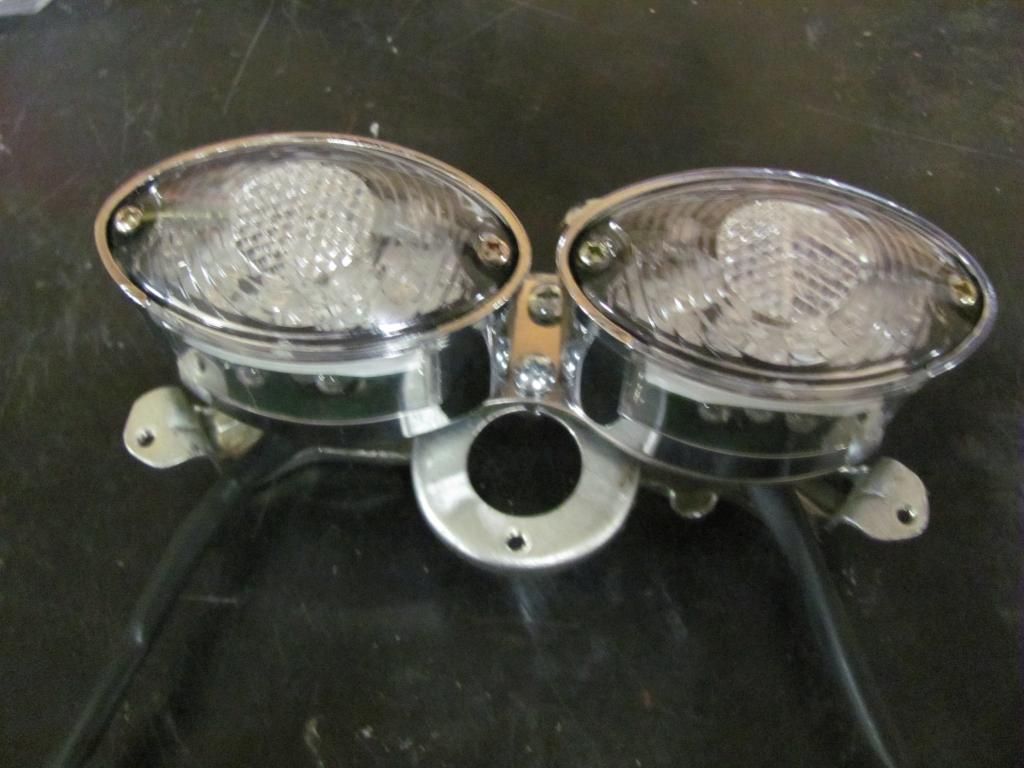
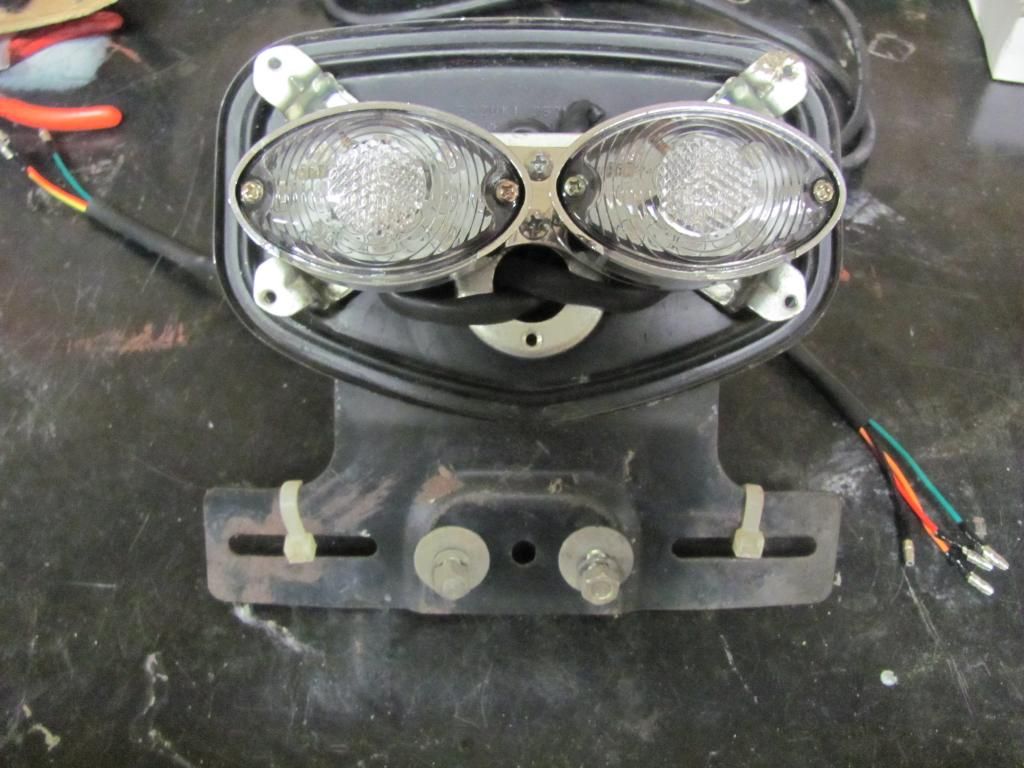
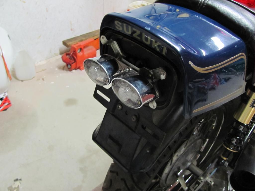
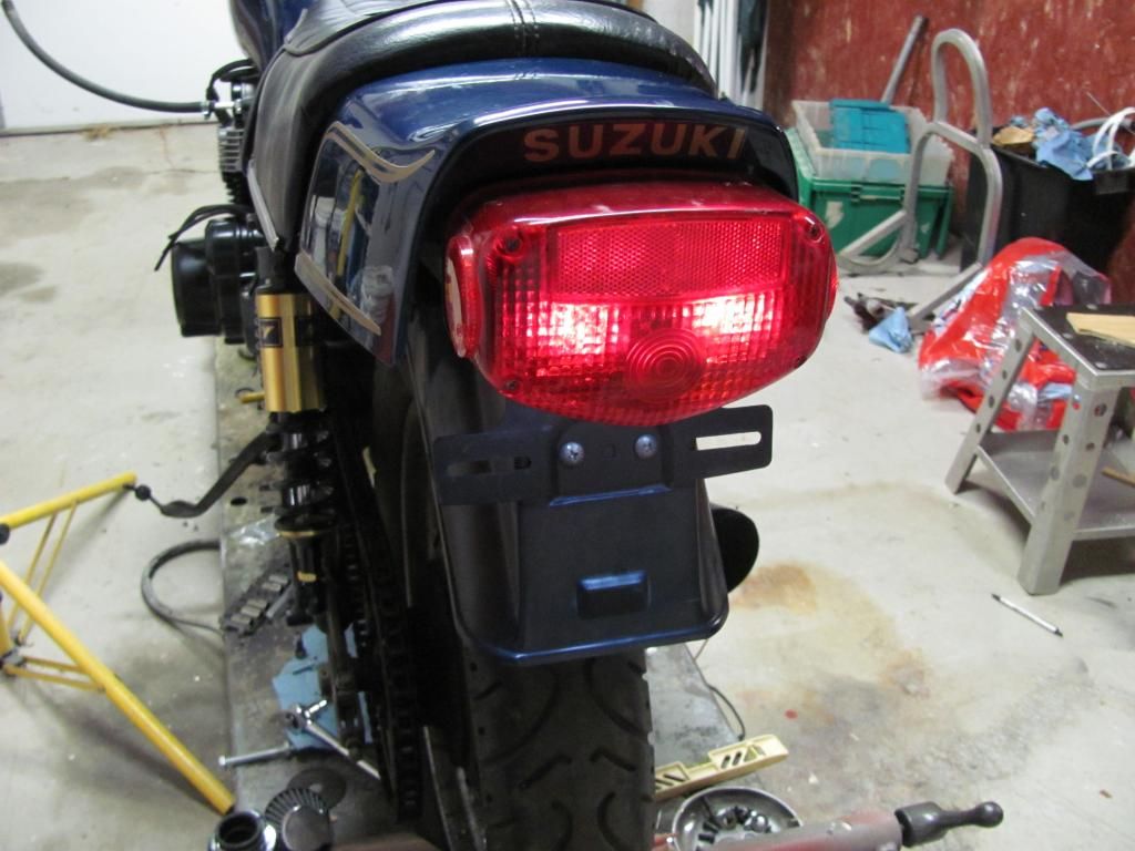
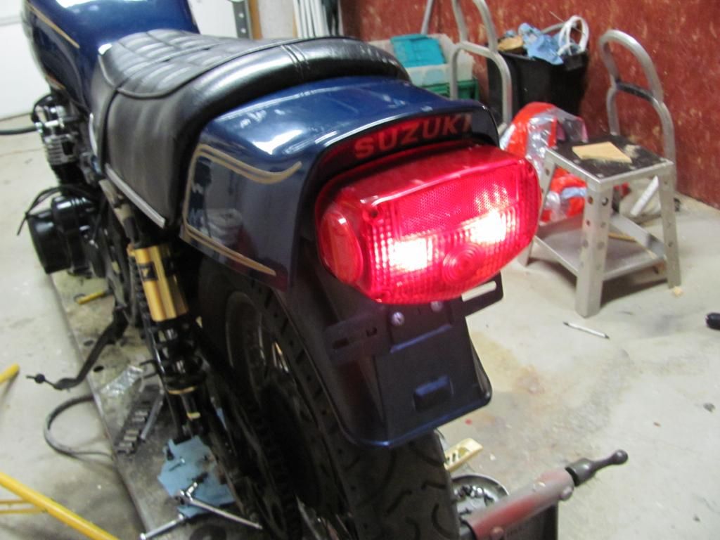
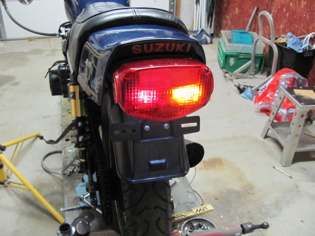
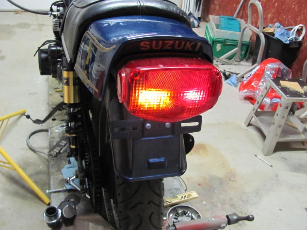
-A dual cat-eye tail light assembly
-New Progressive fork springs (already installed)
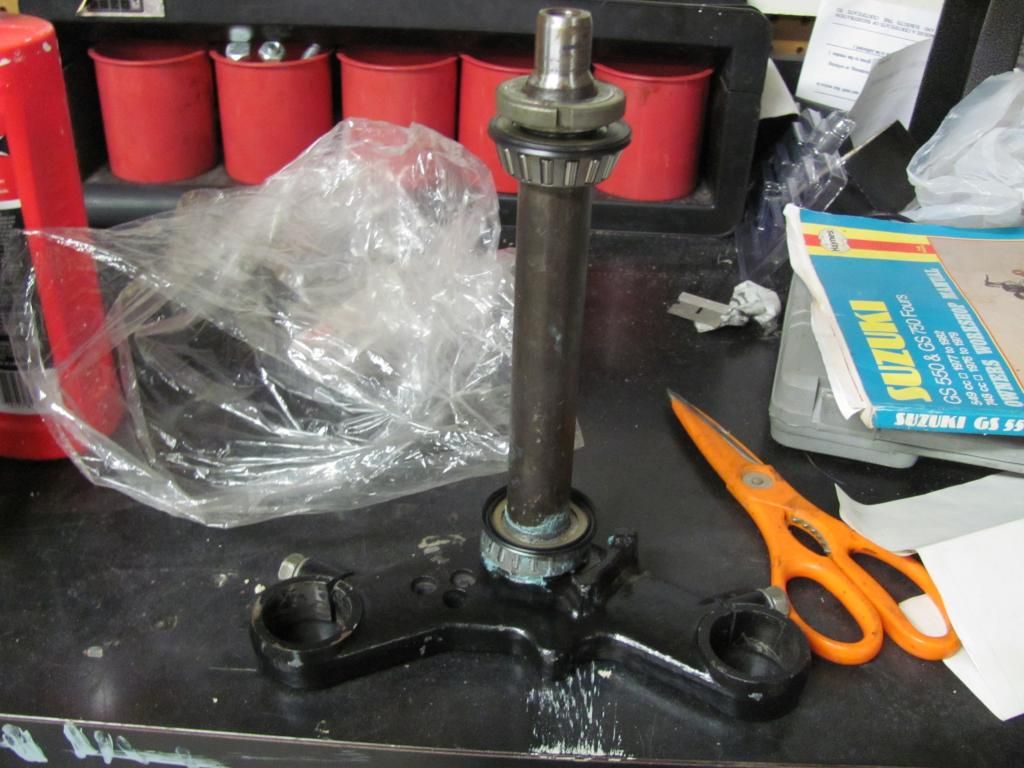
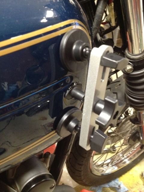
-All Balls tapered steering stem bearings (I need to do some machining to finish the installation per the instructions)
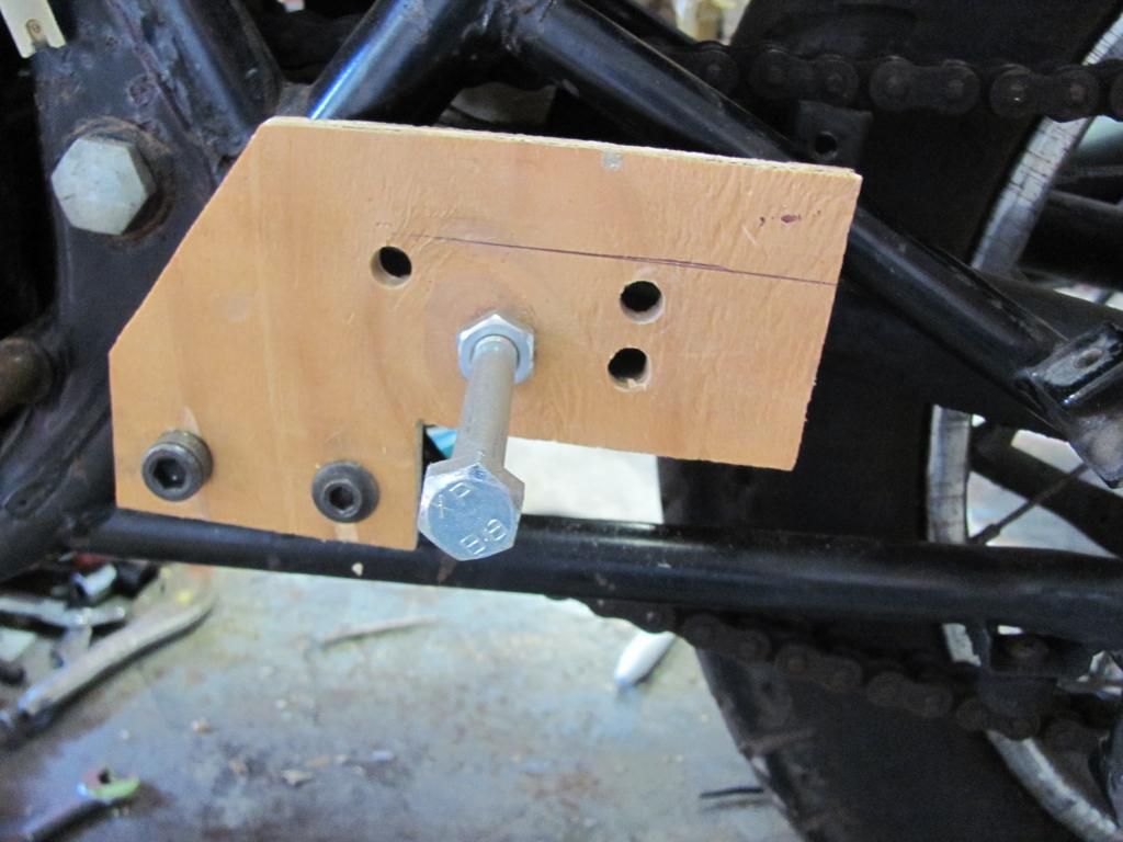
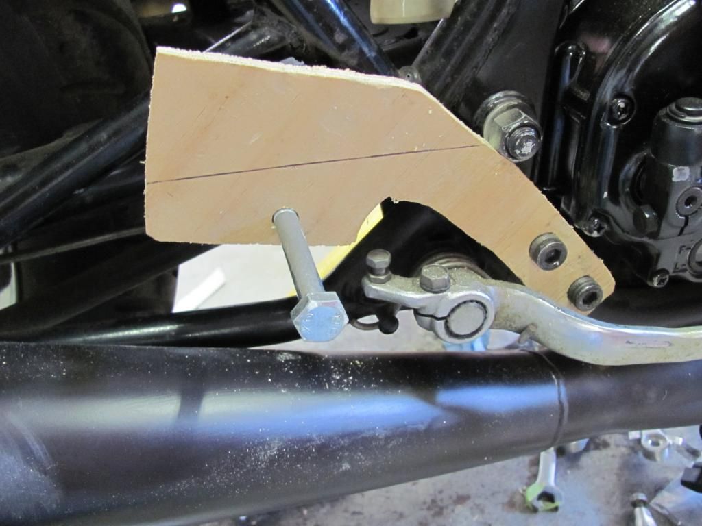
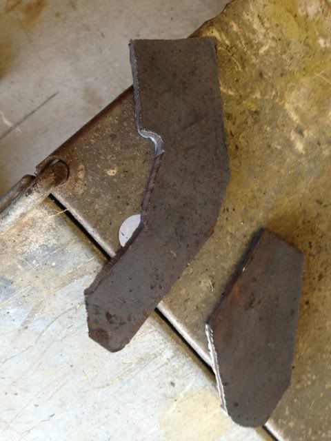
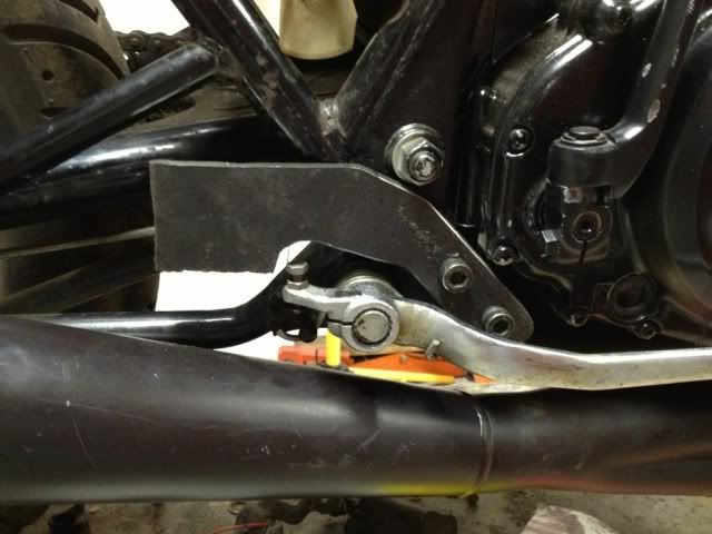
-GSX-R master cylinder and clutch lever (with new clutch cable)
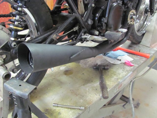
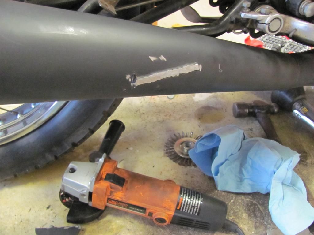
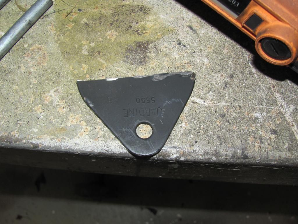
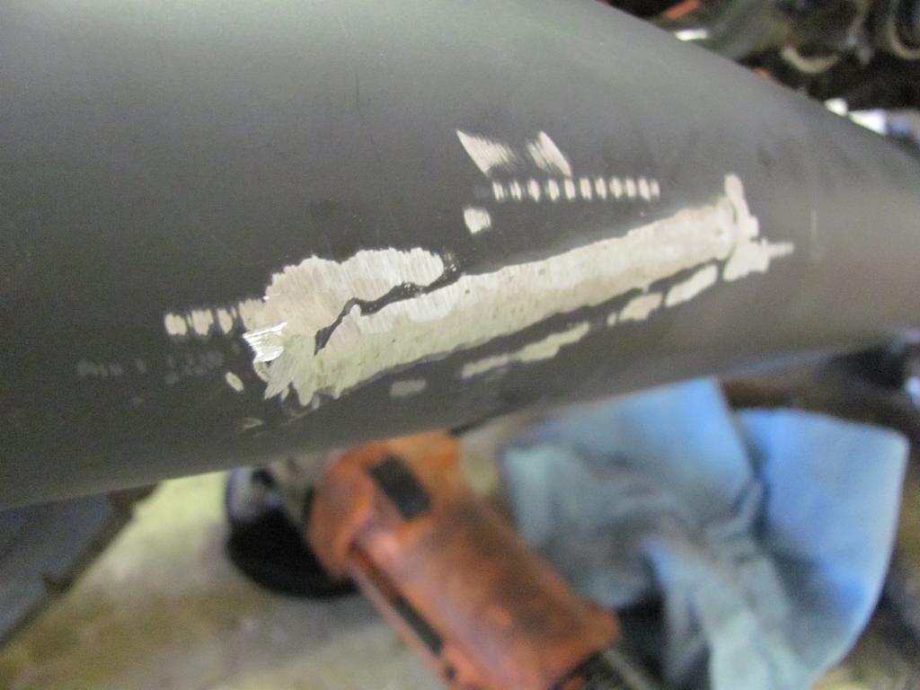
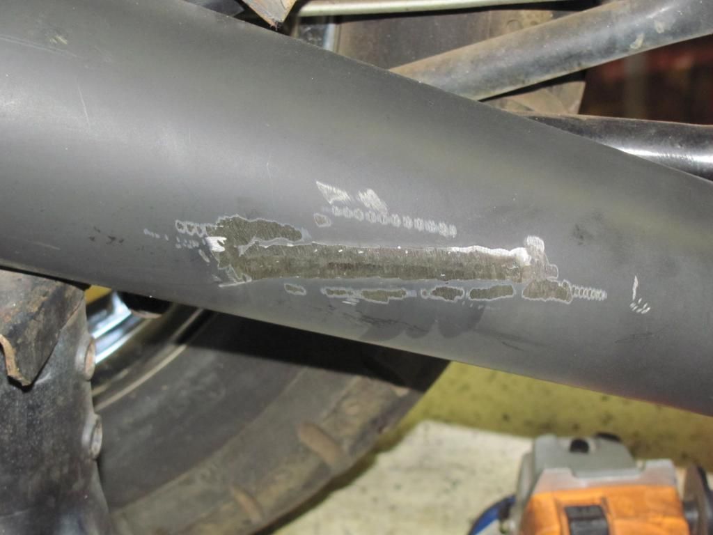
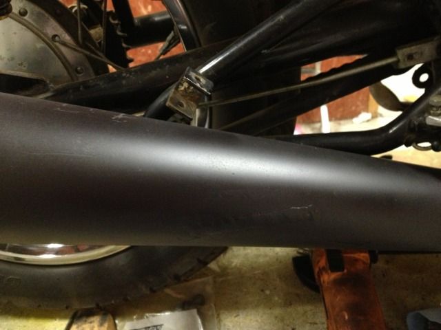
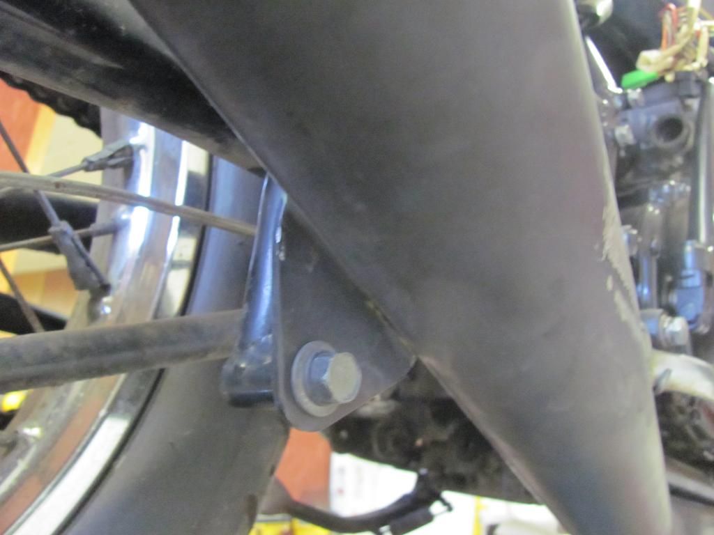
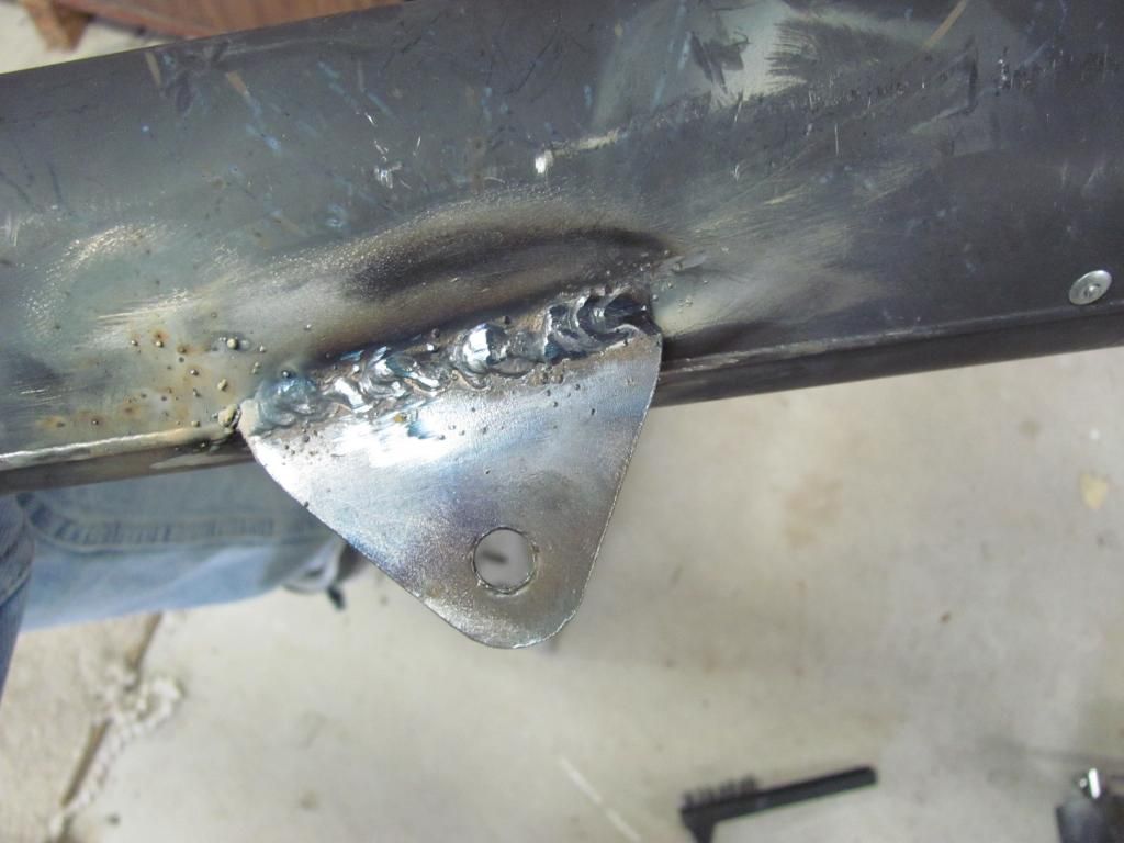
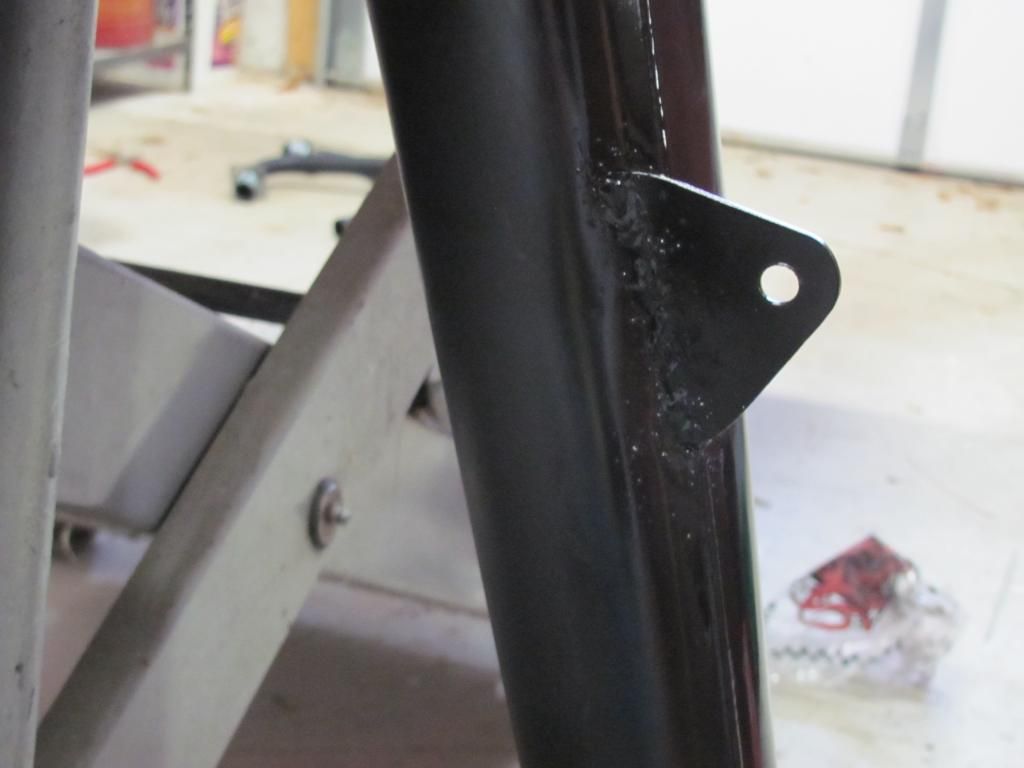
-New N.O.S. Jardine exhaust, but the collector and muffler are for something else (KZ maybe?), so I may be doing some custom exhaust work. (I actually test fit the system and found that the collector and megaphone aren't actually wrong, but the welded-on hanger is in the wrong position. so all it needs is to be cut off and re-welded in the right place.)
 
First, I focused on the two highest priorities - exhaust and carbs

The stock carbs are in HORRIBLE shape, and the previous owner had a set of KZ650 carbs that he put in the parts pile.

GS550 stock carbs:
IMG_2984.jpg


KZ650 carbs:
IMG_2985.jpg


The starter plungers (choke) were stuck in both sets of carbs:
IMG_2987.jpg


So I soaked them am got them cleaned up and freed:
IMG_2988.jpg


I disassembled both sets and installed the KZ carbs on the GS rack:
IMG_2996.jpg


I need to find one emulsion tube for the starter jet on the #1 carb 'cuz it was broken. The GS tubes are the same size, but the height of the cross drilled hoes are different, so I will see if I can find a junk carb for the part before trying the GS one. However it would only affect the operation while choked, so it wouldn't be that big of a deal to use one from the GS carb.
 
Next was the exhaust. My friend said he thought that the collector/muffler that came with the Jardine system he bought were for a different bike. After I test fit the system I don't think that this was the case. It seemed to be correct, except that the hanger bracket is welded in the wrong location:

IMG_2990.jpg

IMG_2992.jpg


It just needed to be cut it off and welded it in the right place.

IMG_2999.jpg

IMG_3000.jpg


Did some grinding:
IMG_3003.jpg

IMG_3006.jpg


A little Hi-temp paint, and it almost disappears:
A41CE028-8644-49FE-BA10-6ECF7B93A556-632-0000010D2E4DAD0A.jpg


A little more work, and it'll be barely visible.

I set it up in the correct position to be welded...
IMG_3010.jpg


After doing a few practice welds, I had to put on my big boy pants, and actually weld the bracket on the exhaust!

Not perfect, but not HORRIBLE:
IMG_3014.jpg


A little paint... (still glossy 'cuz it's wet):
IMG_3018.jpg


Exhaust issue solved!!
 
The cam covers needed a little sumptin':
IMG_3022.jpg


So in keeping with the satin black theme my friend started, I scuffed and painted them:
IMG_3024.jpg

IMG_3034.jpg


I also blasted the exhaust collars and used exhaust paint on them:
IMG_3036.jpg


While I was at it...remember the scar left from the original muffler bracket location?
A41CE028-8644-49FE-BA10-6ECF7B93A556-632-0000010D2E4DAD0A.jpg


I took care of that with more grinding, sanding and paint:
IMG_3035.jpg


The previous owner started to do a tapered bearing conversion on the steering stem, but it needed some machining done to complete the install, and he had pressed on the lower bearing....but hadn't put the lower seal on first! I had to remove the lower bearing, get a new one and had the machining done and the front end was re-assembled:
IMG_3027.jpg
 
I made the decision to buy a set of GS550 carbs rather than try to venture down the tuning nightmare that the KZ650 carbs would present. I might attempt that later, but not until I have a running workable bike and get all the other work done that I want to do.

I got a set of GS550 carbs from Ebay, and rebuilt them:
IMG_3037.jpg

IMG_3038.jpg


I used 85 mains (stock are 80) and #17 pilot jets (stock are 15). With the pods and the exhaust, I figured that would be a good starting point.
IMG_3039.jpg


Now it's almost ready to start making some noise!!
IMG_3040.jpg


...then, I can start really tearing it apart!
 
At this point it was running, but the intake boot o-rings were leaking:
30AC3340-A7FE-427C-BC25-5ADCCFAED77D-4646-000006D6B10CBFEC.jpg


I ordered some Viton seals, but got some Buna ones to install in the mean time. Wile I was at it, I changed to screws from the POS phillips, to socket head:
2FC75372-4F93-4131-B2CB-35111D4096E4-4646-000006D6C54D544C.jpg


With the interim seals in, I was able to get the pilot circuit mostly dialed in...

Next, there was a nice little ding in the tank:
0D148335-90A9-4AE8-B450-88E66793ADD7-5341-0000074244F1282C.jpg


With my little dent puller, I was able to get it to be a smaller ding:
97D9B526-AA14-45D6-92E5-25A07603AA1F-5341-0000074250960128.jpg

421AE690-052B-42DB-9734-C6FF2F35EF9A-5341-00000742704E4A18.jpg


I actually got it even smaller than this picture shows with a little more work.

I didn't like the housing that the gauges were in, so I decided to take off their clothes and run them exposed........but that COLOR! It's gotta go!
C5C7D168-CA81-4657-BAD9-A8EE6049AF7D-5341-000007425BB21DAB.jpg


A little satin paint, and voila!
B6C757E2-9305-4A0B-BA35-C471D4788491-5341-00000742658A64DE.jpg


Now for fabbing up rear set mounts. To do this, I used some 3/8" plywood to mock them up.
IMG_3043.jpg

IMG_3044.jpg


The final shape of the brackets will not be anything like that. The shape will be determined by the hole locations, and minimized as much as possible.

Once I got the positioning right, I realized that the peg and brake pedal will interfere with the kick starter, but I've got a plan for that....
 
I borrowed a plasma cutter to cut out the brackets for the rearsets...

Here's the rough cut:
BA35D9BE-B20C-41DC-8BFC-A3A178290309-10815-00000E1DB578D912.jpg


With some trimming:
C22FA595-26D2-44B0-9015-D58DE05EAF12-10815-00000E1C5D13BC6E.jpg

738C40AB-950D-4396-B35C-9284D0799CB5-10815-00000E1C51559153.jpg


Peg holes drilled, and rearsets installed:
5C3ACFE0-60B0-435F-9CB2-2B8ACB1FC290-10815-00000E1C467673C9.jpg

09EE3433-B7AD-42E4-938C-2E79D662975C-10815-00000E1C3BF37059.jpg


Now that the rearset location is set, I will need to trim the brackets more, and get the linkages laid out. Kris Richardson, from Old School Speed (where I got the rearsets) sent me a shifter side lever that has the linkage arm pointing down. The shift shaft lever cannot be flipped because of a notch on the engine case, so with the rearset arm pointing up, I would need to fab something up on the original shifter linkage. With the one Kris is sending, all I need is a straight rod.


While I had the plasma cutter, I cut up the front fender, as well:
CE974BE4-52A5-43B2-8FEA-9364584D3F6D-10815-00000E1DAAC3C526.jpg

6EFBB641-92EE-4715-BCD3-004F83992A9C-10815-00000E1C68248247.jpg
 
Time for the rear brake linkage set-up:

I cut off the brake pedal:
IMG_3065_zpsa363c092.jpg


Made a tab for the linkage:
IMG_3069_zpsa2cea1d6.jpg


Shaped, drilled and welded the tab to the brake pedal clamp:
IMG_3071_zps341b5c76.jpg


Cleaned it up a bit (had to grind off the rest of the chrome for paint eventually):
IMG_3078_zps839b0089.jpg


Here it is installed with the link attached:
IMG_30722_zpsa3556baa.jpg


...but why, you ask, did I use a shackle with a removable pin instead of a heim joint on the front joint?
Well, I'm glad you asked!* The kick starter cant be used with the rearsets in their normal position:
IMG_30732_zpsa60bd23e.jpg


...so I made it so you fold the peg, and disconnect the linkage (without tools) and flip the brake pedal out of the way, and Voila!* The kicker* is functional!
IMG_3075_zps45c77314.jpg
 
Next, the shifter side:

As I mentioned before, the shifter that was included in the set pointed up, but this would cause issues with the linkage,
09EE3433-B7AD-42E4-938C-2E79D662975C-10815-00000E1C3BF37059.jpg


...so Kris Richardson from Old School Speed sent me a shifter that pointed down:
IMG_3064_zps0d340783.jpg


I drilled off the original ball joint from the shifter link:
IMG_3061_zpsc401a333.jpg


And here it is...
IMG_3089_zps49fd03ae.jpg


Finally, the rearset brackets needed to be trimmed down to get rid of the excess:
IMG_3081_zpsa864c4f6.jpg


With only an angle grinder and a bench grinder....not too bad, if I say so myself:
IMG_3084_zpsb83549b9.jpg


and here it is installed:
IMG_3086_zps9cb70c21.jpg


I got some 1 inch spacers made out of 1-1/4" aluminum round stock to replace the sockets I have between the brackets and the pegs, and the brackets were painted black, but didn't take photos.
 
Originally I intended to get a cafe style seat and tail, but in order to do that I would have to cut the frame or find one that was substantially long and UGLY. I just haven't decided I wanted to make that commitment, yet (no turning back from that one). So I tried to figure out what I wanted to do with the tail. This little gem was in the parts pile that came with the bike, but I HATED the look of it. It is an integrated turn/tail/brake light, but I couldn't figure out how to make it work with any thing I did with the rear.

IMG_3045.jpg


Then I thought, the stock tail on this bike isn't too bad, and the original parts aren't in too bad of shape.....so I thought I'd combine the two!

I gutted the stock tail light and cut the bracket of the cat eye apart:
IMG_3047.jpg


I mounted the cat eyes on the interior bracket that held the old light socket:
IMG_3048.jpg


Then mounted the assembly back on the tail light assembly:
IMG_3049.jpg


Installed the original tail and fender with the new hybrid assembly (still ugly):
IMG_3050.jpg


Then covered it up with the original lens!
IMG_3052.jpg


Wired it up, and Voila...Tail lights:
IMG_3055.jpg

...Brake lights:
IMG_3053.jpg

Right turn:
IMG_3056.jpg

Left Turn:
IMG_3057.jpg


I had get a flasher that will work with the LED's, as well.
 
Next, was the electrical component tray. First the general shape was cut out of cardboard:
AD40CCB7-1317-4827-B93C-C29F298C4186-1566-000004D375FB71C4_zps0126ffe8.jpg


That was transferred onto the sheet metal, and cut out:
03713764-8DF9-451E-BA45-C28D3C571000-1566-000004D3870F5D23_zpscc2e4426.jpg


Using my backyard sheet metal break, I got the bends done...
7439A5C5-8B7F-4652-9356-C81769D39E24-1566-000004D391636574_zpsd5ebf444.jpg


Then I laid out the components where they will end up. Man that Shorai battery is small! (2.25" X 3" X 4", and about a pound):
C7B0B5E7-208D-409F-9E08-29FC23A38070-1566-000004D3A2F4C2E5_zps876cc31c.jpg


The rectifier will end up mounted on the bottom of the tray so it will get plenty of cooling air.

Everything got mounted and the wiring laid out:
IMG_3113_zpsbcf80a5e.jpg


I did have to lengthen the cable from the starter to the starter relay, and make a new negative batt cable, so I had to figure out how to crimp a 6 gauge wire terminal without spending a bunch of money on a crimper.* So I used my AMP crimper in the 10 gauge slot to start the crimp, then finished the crimp in a vise.* Then flowed solder into the crimp for a complete connection.* Ugly, yes, but 100% connected:
IMG_3111_zps0bbe7fb1.jpg

This is where all the electrical components used to be, behind the side panels:
IMG_3093_zpsa1e2a856.jpg


...and this is how it looks, now:
IMG_3123_zps9293cdbe.jpg


Tune in next time when this gauge cluster get fluster chucked! ...or, Fun with LED's
IMG_3110_zpsb3e91dfe.jpg
 
Last edited:
Welcome, nice work on that 550 project. I like that you put in the effort to keep the kick start usable. Reminds me of a Honda TL125 Trials bike a friend has. It has a hooked spring on the swing arm to hold the peg out of the way so you can get a full stroke on the kicker. Otherwise, short stroke only.

I thought I saw an Alabama tag in your parts pile, where ya located?

Buddy
 
Thanks. I am in East Tennessee, but the guy I bought the bike from, bought the bike from a guy in Alabama, LOL.
 
...so the original cluster is an abomination, IMO, so I gutted it and painted the gauges (mentioned in a previous post). I still wanted the indicator lights, so I took the inside housing and flipped it upside down:
IMG_3099_zps27bd9934.jpg


Then I cut a plate out:
IMG_3100_zps58dee6e1.jpg


and mounted it on the housing:
IMG_3101_zpsa260aa41.jpg


One of the light socket holes was unused, so I used it as a mounting point:
IMG_3104_zpsd0d712ac.jpg


Drilled holes for the LED's and painted it black:
IMG_3129_zps74a4c51e.jpg

IMG_3134_zpse76b40fb.jpg

IMG_3135_zpsddbc20d1.jpg


And done!
IMG_3140_zps0c43117e.jpg

IMG_3136_zpse07ed6c4.jpg
 
Looking good! Great job on those rearsets, they look super professional :clap:
 
good work! glad you grinded the rest of the welds off the exhaust. and that bike is going to look sweet with all the original body work with rearsets and low bars just how i like it!... if you leave it that way.

and we need a shot of the whole bike! unless its in pieces.
 
Update time:

These cheap Chinese RFY shocks were included in the pile-o-parts I got with the bike.
IMG_3143_zps6ddf9263.jpg


CrazyPJ, from one of the Cafe racer forums is the only person that I have found that has rebuilt these things, and he states that they are not bad, but out of the box, they don't have enough oil, or Nitrogen. And I found that to be the case with mine...

....so it's "service time". And a HUGE thanks to PJ for answering my few...OK, a dozen....questions. Between PJ's help and the following video from Youtube, I was ready to tackle a set of shocks for the first time.

http://www.youtube.com/watch?v=5UIDJt-OyEE

First, I bough an adjustable pin spanner wrench I found on eBay for 6 bucks (also good for my angle grinder)
IMG_3151_zpsa140b1f7.jpg


Next, I need a spring compressor..which I don't have...but I do have a bead breaker on my tire machine:
IMG_3144_zpsf9ef68ba.jpg

..and the center stand that was removed from the GS...
IMG_3145_zps5952c8f1.jpg

...and some flat stock...and a vise...
IMG_3146_zpscdddec13.jpg


Some creative use of a tie down to stabilize it, and now it's a make shift spring compressor:
IMG_3149_zps3985166b.jpg


With the spring off and the seal retainer removed (with the pin spanner wrench) I cut an 8" piece of tubing off of an old porch swing this is in the scrap heap. With the spring seats, a couple of washers and the shock shaft nut, I used the tubing as a puller to pull the shaft seal.
IMG_3150_zpsd3bef399.jpg


Here it is disassembled:
IMG_3148_zpsda2b0e83.jpg


To reassemble, I followed the youtube video, with a few small modifications for the differences in design. In Crazy PJ's build, he drilled and tapped the shock body to install a bleed screw in this spot:
IMG_3154_zps6104923e.jpg


I didn't have a way to counter bore the hole to accept an o-ring, so I didn't do it. It isn't necessary, but it is a great idea, and allows you to get every bit of air out of the shock.

Here they are re-assembled. I took them to a tire store and had them charge them with 75 psi of Nitrogen.
IMG_3156_zps07d826c6.jpg


Job done. Oh, I used 10 wt fork oil. We'll see how well it works. I might need to go up or down in weight.
 
Where did you get those shifter linkage ends? I need to modify mine as well and yours looks much easier.
 
Back
Top