I hope Jim (Posplayr) will shed some "light" on this.
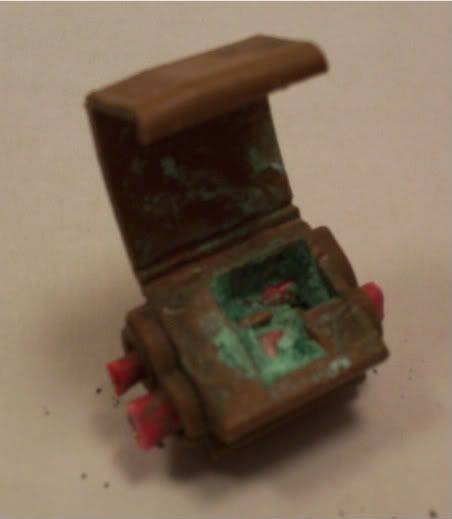
I was trouble shooting the inop dome light in my truck topper. Easy. Check the voltage at the bulb socket. 12.5 VDC. Bad Bulb. Nope. ???? There is 12.5V at the socket ! Two bad bulbs ? Nope. WTF. 12.5VDC on both sides of the fuse. A+ wire ohms out to the light socket. Bad ground ? Nope. Ground wire ohms out to the light socket. WTF !!! Crawled under the truck and found this badly corroded splice. Replaced it with a new splice and....:idea:.
How does the corrosion allow voltage but resists current ?

 ^o
^o


") :idea:
:idea: 
")
