• Required reading for all forum users!!!

    Welcome!
    Register to access the full functionality of the GSResources forum. Until you register and activate your account you will not have full forum access, nor will you be able to post or reply to messages.

    A note to new registrants...
    All new forum registrations must be activated via email before you have full access to the forum.

    A Special Note about Email accounts!
    DO NOT SIGN UP USING hotmail, outlook, gmx, sbcglobal, att, bellsouth or email.com. They delete our forum signup emails.

    A note to old forum members...
    I receive numerous requests from people who can no longer log in because their accounts were deleted. As mentioned in the forum FAQ, user accounts are deleted if you haven't logged in for the past 6 months. If you can't log in, then create a new forum account. If you don't get an error message, then check your email account for an activation message. If you get a message stating that the email address is already in use, then your account still exists so follow the instructions in the forum FAQ for resetting your password.

    Have you forgotten your password or have a new email address? Then read the forum FAQ for details on how to reset it.

    Any email requests for "can't log in anymore" problems or "lost my password" problems will be deleted. Read the forum FAQ and follow the instructions there - that's what we have one for...

  • Returning Visitors

    If you are a returning visitor who never received your confirmation email, then odds are your email provider is blockinig emails from our server. The only thing that can be done to get around this is you will have to try creating another forum account using an email address from another domain.

    If you are a returning visitor to the forum and can't log in using your old forum name and password but used to be able to then chances are your account is deleted. Purges of the databases are done regularly. You will have to create a new forum account and you should be all set.

Critique my diagram

  • Thread starter Thread starter computronic2040
  • Start date Start date
C

computronic2040

Guest
Hello all,

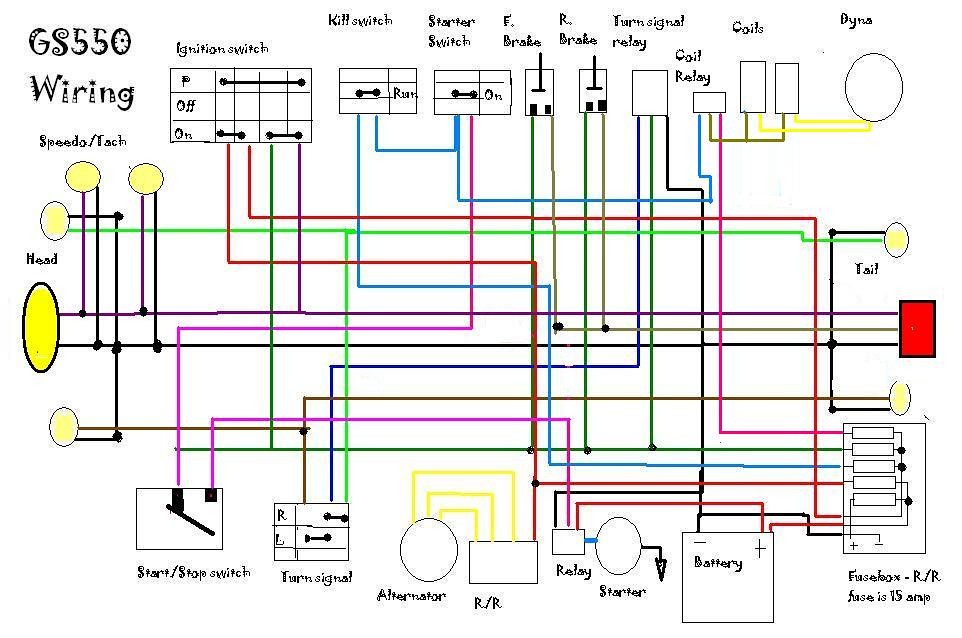
It has been a looong time since I have posted, but I am trying to get this GS550 back together. I am wondering if I even need to do the relay mod for the coils, and how are people wiring their 6 wire honda r/r's (sense wire?). I am redoing/simplifying the wiring diagram to include:


- Lights always on
- 6 wire honda r/r
- dyna ignition
- stock coils
- Shorai mini battery

(someone please help with pics, I am kind of an idiot with this stuff)

10994164245


http://www.flickr.com/photos/22520763@N02/10994164245/

I have eliminated: light hi/low/on/off, gear position sensor, oil light/sensor, kickstand switch, turn signal indicator, and a bunch of other crapola.

I am bringing the bike in from Nevada (haven't registered it here yet). Has anyone gone through the CA inspection? What are they looking for (running lights, horn, etc,) that might not be on this diagram?

Thank you!
 
Last edited:
I can't help you with the wiring diagram but I have broughts bike into California from Nevada. I had a title signed by the registered and the bike had all the equipment that came with, such as lights, speedo, ect. They verified that the serials numbers of the frame and engine matched the paperwork. You'll need to bring the bike to DMV for this verification. If it's tags aren't current you'll need to trailer it to DMV. If the bike is a "work in progress" and not ready for the road, just get the title transfer taken care of and put it on "Non Operational" status. The will check "Insurers" to see if you have a policy for this bike after you have registered it for the road. If none are found to insure you, they will void your resisteration, fine you and over time, if ignored, can amout to more that the bike is worth. If your going to DMV in the "City" you may want to see if you can make an appointment. I've heard horror stories of long lines in large towns. Good luck. It's no big deal if you are polite and have paperwork for the bike.

cg
 
Critique the diagram? Sure, be happy to. :D

1. First of all, the non-stock colors will make tracing and trouble-shooting a bit more difficult. The only wire that appears to be the stock color is the right turn signal.

2. There is an unnecessary "Start/Stop switch" between the battery and the starter. The solenoid (called "Relay", next to the starter) is all you need there.

3. The green wire that extends to the left of the second fuse goes past connections that lead to the turn signal relay, brake switches and tail light (in the ignition switch), then on to ... what?

4. Black wire on relay near starter goes up to the turn signal relay. That one really has me baffled. Might be a ground, but connections with other "ground" wires don't line up very well, making it hard to tell.

5. There are grounds missing from a few items.

6. You will eventually regret not having the ability to use high beam on the headlight.

.

This was probably a good Exersize for learning about the GS electrical but restoring the original harness with the factory wire colors would be much preferable.

I should mention that given the amount of effort in redoing the harness that integration of the SSPB would be a good option.
 
Last edited:
You should also label the fuses in that block. You want a 15A fuse on things that go directly from the battery other than the hvy wire to the starter (so main fuse, coil relay), the other circuits can use 10A fuses. The basic trinity for the 10A fuses are ignition, headlight/tail-light, and horns/signals. Maybe that's what youve done, here, but I cannot quite follow the wire colors.

Also, does the turn signal relay draw straight from the battery? If so, why?

Edit: also the Dyna needs a power source that feeds it whenever the ignition is on (e.g., tied into the coil wire, or the tail-light). Your diagram seems to send the black and white wires from the coils to the Dyna, but no hot wire to power the Dyna itself.
 
Last edited:
Thanks for all of the replies!
- the turn signal relay has a common ground in the origonal diagram, so did the starter relay - soi just plugged them into the ground wire.
- the start/stop switch is just the "starter disconnect switch" in the original diagram.
- mspaint is why the colors don't match, wires don't line up completely and dead end (sorry)
- I will plump in the high beam
- how does everyone get the best voltage at the coils?
- what is the SSPB?
The "starter disconnect switch" is the clutch "safety" switch. That can be bypassed with no problems.

MS Paint is better than you are giving credit.

Best voltage at the coils is by simply ensuring good, clean contacts between the battery and the coils. If you are doing new wires and connectors, that will be enough.
For those that are too lazy to clean their connectors, they apply a "Band-Aid" called the "coil relay mod" to apply current straight from the battery to the coils, instead of routing it through all the old, dirty connectors.

The SSPB is the Solid State Power Board that Posplayr is creating. It is not a cheap item, but probably well-worth the cost for all the headaches it will eliminate.

.

Using a coil relay = lazy

Installing a Solid State Power Box (which includes a coil relay and other mechanisms to eliminate dirty connections) = worthwhile

:rolleyes:
 
Installing a Solid State Power Box (which includes a coil relay and other mechanisms to eliminate dirty connections) = worthwhile.
It has been a while since I looked at the drawing for the SSPB, but I don't remember a relay specifically for the coil. :-k

I seem to remember more of a relay that would provide power to the whole box, which would then distribute to the coils, but I could be wrong (again).
icon_shrug.gif


EDIT: I was wrong. :eek:

Yep, I looked at the diagram for the box and found that it actually has separate relays feeding each fused circuit. :D

.
 
Last edited:
It has been a while since I looked at the drawing for the SSPB, but I don't remember a relay specifically for the coil. :-k

I seem to remember more of a relay that would provide power to the whole box, which would then distribute to the coils, but I could be wrong (again).
icon_shrug.gif


EDIT: I was wrong. :eek:

Yep, I looked at the diagram for the box and found that it actually has separate relays feeding each fused circuit. :D

.

Would Posplayr do anything less?
 
Has anyone gone through the CA inspection? What are they looking for (running lights, horn, etc,) that might not be on this diagram?

Thank you!

I tried to go through the wiring on my bike whilst in California and I searched for Suzuki Loom and started diggin in....I documented this...;)

circuit_diagram.png
 
Ha! That is rad, and not too far off from the crappy wiring job I had on it previously.
 
...............

Looks like you really did some work there to make you own schematic.

Even the stock R/R will need a ground.
If use a 5 wire R/R it too will need ground, and the "sense" connected to a switched "hot" wire, such as the brake light circuit before the brake light switch.

Interesting that you are trying to simplify things and remove unnecessary stuff (and consider oil pressure and neutral to be unnecessary crapola), yet bother to keep the "park" stuff from the ignition switch to the tail light
..and I see you have that going to more than just the tail light.


.
 
Last edited:
Ah, ok. So the sense wire is what tells the r/r to start sending voltage?
I was going to relocate it to the bottom yoke of the triple tree for max cooling. Thanks for the input on grounds. If I have learned one thing from working on old bikes, it is start from the grounds and work up from there!
 
Back
Top