• Required reading for all forum users!!!

    Welcome!
    Register to access the full functionality of the GSResources forum. Until you register and activate your account you will not have full forum access, nor will you be able to post or reply to messages.

    A note to new registrants...
    All new forum registrations must be activated via email before you have full access to the forum.

    A Special Note about Email accounts!
    DO NOT SIGN UP USING hotmail, outlook, gmx, sbcglobal, att, bellsouth or email.com. They delete our forum signup emails.

    A note to old forum members...
    I receive numerous requests from people who can no longer log in because their accounts were deleted. As mentioned in the forum FAQ, user accounts are deleted if you haven't logged in for the past 6 months. If you can't log in, then create a new forum account. If you don't get an error message, then check your email account for an activation message. If you get a message stating that the email address is already in use, then your account still exists so follow the instructions in the forum FAQ for resetting your password.

    Have you forgotten your password or have a new email address? Then read the forum FAQ for details on how to reset it.

    Any email requests for "can't log in anymore" problems or "lost my password" problems will be deleted. Read the forum FAQ and follow the instructions there - that's what we have one for...

  • Returning Visitors

    If you are a returning visitor who never received your confirmation email, then odds are your email provider is blockinig emails from our server. The only thing that can be done to get around this is you will have to try creating another forum account using an email address from another domain.

    If you are a returning visitor to the forum and can't log in using your old forum name and password but used to be able to then chances are your account is deleted. Purges of the databases are done regularly. You will have to create a new forum account and you should be all set.

Minimal 550 Bobber Schematic

posplayr

Forum LongTimer
Past Site Supporter
TGSR Superstar
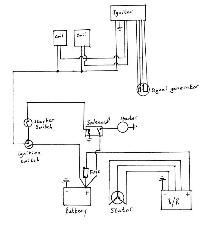
I was asked (and was paid $20 Wahoo) to put together a schematic for a GS550 Bobber project. I followed the GS550 Suzuki electrical design (mostly). I used the last schematic in the manual which is located in Bike cliff's website. The schematic could be made even simpler, but if it omits fusing and proper grounding then in my view it is "too simple". The schematic is intended to be taken literally as far as the physical layout and connections of the harness. So check the notes section that goes with the letters on the schematic and make note of all Ground symbols. Frame ground and case grounds have different symbols. The black dots show when connections between wires should be made; otherwise the wires are not connected. I used the OEM colors for each circuit as best I could.
The items included in the schematic are:
?Battery
?Fuse box (stock GS)
?Ignition switch (2 wire after-market)
? Kill switch and Starter switch (button) (OEM)
?Starter
?Starter Solenoid
?550 Igniter
?Coils
?Stator
?R/R (5 wire)
?Frame grounds
?Ignition Kill Switch

Some Notes:

  • There are no lights/blinkers included in the schematic. Obviously they should be added.
Generally I would not run the stator leg through the handlebar switch (this is generally recommended on all GS's) but rather have the headlamp on all the time and direct connect the 3 stator wires to the R/R.
The OEM fuse box has unused circuits for things like lights.
  • No gages? You can add a wires for the coil (-) for the electronic tach, lights. (I left a ground in the harness running from front to back)
  • This could be modified easily for a Coil relay mod. This would be simple to do now. (I left it out)
  • There is an extra ground wire because some people may not have the starter solenoid and R/R mounted on the same plate. If you relocate igniter, solenoid, R/R to the same plate then things get simpler. Just make sure the Star grounding configuration at the R/R is maintained.
  • Any other accessories can be added to the extra circuits shown
The pdf file was created in Powerpoint so if someone wants that powerpoint file (PM me) they can change the colors of the wires for any other color sets they might want. The pdf of the version using stock colors is below.

The various symbols came right off the 550 schematic so if you study that and this you should be able to make decisions with respect to reusing old connectors or just wiring directly. Anything not connected is obviously not being used.

EDIT: THIS IS BAD LINK:

Here is the original powerpoint file that you can modify as you like. This includes a coil relay mod and some other changes.

http://www.keepandshare.com/doc/4359880/550-schematic-reva-ppt-624k?da=y


A little discussion on lighting

http://www.thegsresources.com/_foru...et-lights-wiring-issues&p=2175395#post2175395
 
Last edited:
Looks good - You definitely earned the 20$;)

One tiny comment/suggestion though:

At the earlier 550 (with separate rectifier and voltage regulator), one of the stator wires was only connected when the headlight was on. Obviously the headlight is permanetly off in this setup.
For the more modern rectifier/regulators it is not a problem, but would it be an idea, to omit one of the stator wires and keep the heat down anyway.

Best Regards
Stig

Hi Stig,
Yes you will note that I left all the lights and controls out as was requested but you bring up a good point about the headlamp control and it's coupling to the charging system.

Generally I would not run the stator leg through the handlebar switch (this is generally recommended on all GS's) but rather have the headlamp on all the time and direct connect the 3 stator wires to the R/R.

I'll add a note to the first post.

Jim
 
Here is a color code list generated by BassCliff which should also be very helpful
 
G'day. I'm about to rewire the GS1100 and I'm going to use this wiring diagram. One question I have with the Lights, indicators, and customised tacho that I'm hooking up, Is it ok to run these off the one fuse? Or is that a bad idea?

So I'm thinking, One 10amp fuse, that would go to both indicator relays, one to the headlight switch, and one to the brake switch...
Thoughts?
 
Do you ever ride at night? :-k

Are you comfortable with the concept of hitting the brakes, having some wire short out (blowing the fuse) and losing your headlight while at speed? :eek:

Not only that, but your headlight draws about 5 amps. Your coils draw about 8 amps. That alone would blow your fuse.

.

yea, rather than reinvent the wheel figure out what was on the same circuit and reinstall that way.
 
Thank you. I will be using this on my bike over the winter. As the wiring is in sad shape and I have OCD when it comes to clean simple wiring lol
 
The link is not working and I am about to start the wiring on my bike. Anyone have this saved somewhere else?
 
I know Jim isn't crazy about this crude drawing because it doesn't show ground points but it should help you connect the things that are really needed.
GSRdiagram.jpg
 
Excellent schematic. Anyone have any idea where else the grounds would go?
 
How about this?

How about this?

How about this, from the book. Hope it's viewable. I can't figure out how to post a larger pic.
 
Thanks, Steve. I did this as an exercise to help in diagnosing a problem, and I keep fiddling with it and making new ones. Isolating each system helps in understanding how it all should work.
 
Back
Top